


Introduction to the DME64N/24N
Signal Types
DME64N/DME24N Owner’s Manual
11
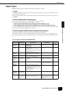
Signal Types
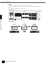
DME64N/24N audio system signals can be broadly categorized as follows.
1 Audio
The DME64N/24N will be required to send and receive audio signals to and from other DME series units as
well as other audio equipment.
Audio signal transmission and reception will occur primarily via the [INPUT] and [OUTPUT] connectors on
the DME24N.
2 Control signals within a device group
Device group control signals control all DME series devices in the group.
There are two types of device group control signals, as follows:
• Control signals between the computer and the group master DME series unit
• Control signals between the group master DME series unit and the other DME series units
You can use the DME Designer application to control the entire device group, such as sending components
to the devices and setting the parameters as required.
3 Control signals between devices outside the device group
These signals provide communication and control between individual devices.
Included in this category are MIDI messages transferred between [USB] connectors, GPI signals trans-
ferred between [GPI] connectors, and remote head amp control signals handled via the [REMOTE] connec-
tor.
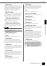
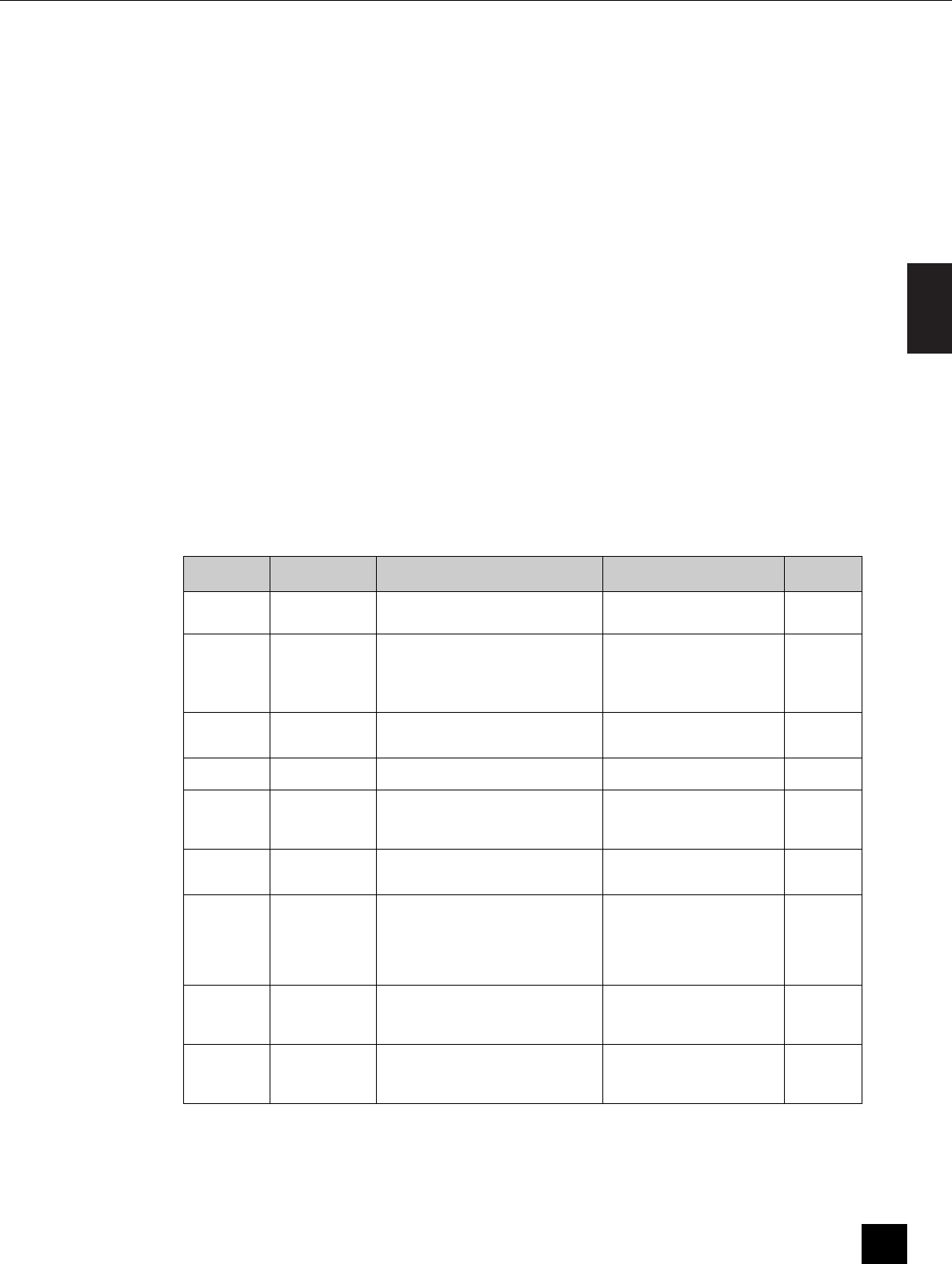
Type of signals handled by the DME64N/24N
Connector Audio Signal Device Control Word Clock
Reference
Page
[USB]
Connector
– • Control signals between computer and
DNE64N/24N
• MIDI messages
–22
[NETWORK]
Connector
– • Control signals between computer and
DNE64N/24N
• Control signals between DME series
unit.
• Control signals with a controller such as
an AMX or Crestron
–23
[MIDI]
Connector
– Control signals (MIDI commands)
between MIDI controller and DME64N/
24N.
–30
[GPI]
Connector
– Control signals between GPI device (GPI
controller, etc.) and DME series unit
–33
[CASCADE]
Connector
(DME64N
only)
32 channels of
input/output.
Control signals from the digital mixer to
the DME64N
Word clock transmission and
reception to and from other
devices.
31
[WORD
CLOCK]
Connector
– – Word clock transmission and
reception to and from other
devices.
32
[REMOTE]
Connector
– • Control signals to/from an external
device (such as AD8HR head amplifier)
• Control signals for a digital mixer and
internal head amp
• Control signals with a controller such as
an AMX or Crestron
• MIDI messages
–28
(Audio I/O
Connectors)
(DME24N
only)
8 channels of
input and output.
––26
(I/O Slot) Number of I/O
channels depends
on card.
Serial signal transmission/reception
(depending on function of card).
Word clock transmission and
reception to and from other
devices (depending on function
of card).
27