


38
1
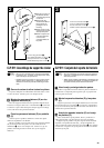
NOTE
• We do not recommend attempting to assemble the
Clavinova alone. The job can be easily accomplished,
however, with only two people.
• Use only the screws provided or replacements of
exactly the specified size. Using screws of the wrong
size can result in damage to the instrument.
Z
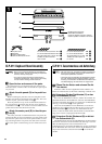
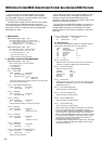
Open the box and remove all the parts.
On opening the box you should find the parts shown in the
illustration. Check to make sure that all the required parts are
provided.
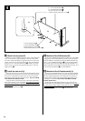
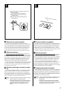
X
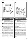
Assemble the side panels (D) and feet (E).
Secure the feet (E) to the side panels (D) with the 5 x 40
millimeter long gold-colored screws 1 (3 each), making sure
that the cutouts on the feet face the bracket side of the side pan-
els.
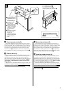
C
Attach the side panels (D) to the pedal box
(C).
Before installing the pedal box, untie and straighten out the
bundled cord attached to the bottom of the pedal box.
Place the pedal box on top of the brackets attached to the side
panels (D), and attach using the four 6 x 20 millimeter round-
head screws 2 — two screws on each side. Make sure the pedals
extend in the same direction as the feet.
HINWEIS
• Wir raten davon ab, das Clavinova alleine zusammenzu-
bauen und aufzustellen. Zwei Personen können diese
Arbeit jedoch problemlos ausführen.
• Verwenden Sie ausschließlich die mitgelieferten Schrau-
ben oder Ersatzschrauben identischer Größe. Die Ver-
wendung von Schrauben mit abweichenden Maßen kann
eine Beschädigung des Instruments zur Folge haben.
Z
Öffnen Sie den Karton und nehmen Sie alle
Teile heraus.
Im Karton sollten die oben abgebildeten Teile enthalten sein.
Prüfen Sie zunächst bitte, ob alle Teile vollständig vorhanden sind.
X
Schrauben Sie die Seitenwände (D) und die
Füße (E) zusammen.
Machen Sie die Füße (E) mit den vier langen goldenen Schrau-
ben (5 x 40 mm) 1 (jeweils 3 Schrauben) so an den Seitenwänden
fest, daß der Ausschnitt am jeweiligen Fuß unter dem Winkelblech
an der Seitenwand zu liegen kommt.
C
Befestigen Sie die Seitenwände (D) am Pedal-
kasten (C).
Bevor Sie den Pedalkasten montieren, nehmen Sie zunächst das
gebündelte Kabel aus dem Pedalkasten, entfernen den Kabelbinder
und ziehen das Kabel dann gerade aus.
Setzen Sie den Pedalkasten auf die Winkelbleche der beiden
Seitenwänden (D), und schrauben Sie ihn dann mit den vier
Halbrundschrauben (6 x 20 mm) 2 fest (jeweils zwei Schrauben
links und rechts). Achten Sie dabei darauf, daß die Pedale in
dieselbe Richtung weisen wie die vorspringenden Teile der Füße.
CLP-511: Zusammenbau und AufstellungCLP-511: Keyboard Stand Assembly
5 x 40 mm long gold screws
Lange goldene Schrauben
(5 x 40 mm)
Vis longues dorées de 5 x 40 mm
Tornillos dorados largo
de 5 x 40 mm
6 x 20 mm round-head screws
6 x 20 mm Halbrundschrauben
Vis à tête ronde de 6 x 20 mm
Tornillos de cabeza redonda
de 6 x 20 mm
4 x 12 mm round-head screws
4 x 12 mm Halbrundschrauben
Vis à tête ronde de 4 x 12 mm
Tornillos de cabeza redonda
de 4 x 12 mm
4 x 20 mm tapping screws
4 x 20 mm Schneidschrauben
Vis auto-taraudeuses 4 x 20 mm
Tornillos de autoenrosque de
4 x 20 mm
6 x 20 mm flat-head screws
6 x 20 mm Senkschrauben
Vis à tête plate de 6 x 20 mm
Tornillos de cabeza plana de
6 x 20 mm
Bundled pedal cord inside
Gebündeltes Pedalkabel
Cordon de pédalier enroulé à l’intérieur
Cable de pedales enrollado en el interior
DD
A
B
C
EE
x 6 1
x 4 2
x 2 3
x 4 4
x 4 5
● Cord holders x 2
● Kabelhalter x 2
● Serre-câble x 2
● Soportes de cable x 2
● AC power cord
● Netzkabel
● Cordon d’alimentation
● Cable de alimentación de CA