


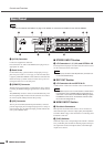
Controls and Functions
10 IMX644 Owner’s Manual
NOTE
• Refer to “Connectors and Cables” on page 13 for details on connectors and cables for use with the IMX644.
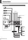
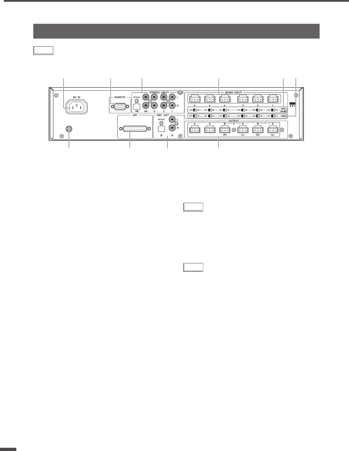
1 [AC IN] Connector
Connect the supplied AC cable here.
First connect the AC cable to the IMX644, then plug it into an
appropriate AC outlet.
2 Earth Screw
For maximum safety, please earth the unit properly. The sup-
plied AC power cable is a 3-wire type, so if the AC outlet used
is properly earthed the IMX644 will be earthed as well. Hum and
interference may by further reduced in some cases by also con-
necting the earth screw to an earth point.
3 [REMOTE] Connector
This RS-232C connector allows communication with a comput-
er running the IMX644 Manager application or external control-
lers.
The [REMOTE] connector cannot be used simultaneously with
the front-panel [USB] connector. If both connectors are connect-
ed, the front-panel [USB] connector takes priority.
4 [GPI] Connector
This 25-pin D-sub GPI (General Purpose Interface) connector
provides eight input ports and eight output ports for a variety of
control signals, plus one dedicated output port that indicates the
unit’s power ON/OFF status.
■ STEREO INPUT Section
5 L/R Connectors 1, 2, 3, 4A, and OPTICAL 4B
The output from CD players and other stereo line-level sources
can be connected to these stereo inputs.
NOTE
• The 4A (L/R) connectors and 4B (OPTICAL) connector can-
not be used simultaneously.
■ REC OUT Section
6 L/R Connectors A and OPTICAL B
A CD recorder or other stereo recorder can be connected here.
NOTE
•A feedback loop can occur if a CD recorder or similar device
is connected to both a STEREO INPUT and the REC OUT
connectors. In such cases use the IMX644 Manager applica-
tion MATRIX controls to turn the OUTPUT channel to REC
OUT connector assignment off.
■ MONO INPUT Section
7 Euroblock Connectors
Microphones and similar mono sources can be connected to
these balanced input connectors. High-quality head amplifiers
are built in. Refer to page 13 for instructions on connecting to the
Euroblock connectors.
8 [PAD] Switches
When ON, input to the corresponding mono channel is attenuat-
ed by 34 dB. The pads are ideal for matching input sensitivity to
the output from wireless microphone tuners and similar high-
output source devices.
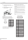
Rear Panel
1
246)
35 7 89