


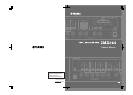
Controls and Functions
IMX644 Owner’s Manual
9
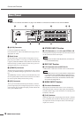
■
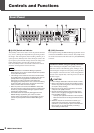
MONO INPUT Section
3
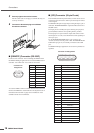
Matrix Indicators
The outputs to which each mono input are assigned are displayed
by orange indicators.
4
[SIGNAL/PEAK] Indicators
These indicators light green when a signal is detected at the cor-
responding mono input.
The [SIGNAL/PEAK] indicators also light red to indicate exces-
sive input level at the corresponding input. If excessive input
level is indicated either reduce the output level of the connected
source, or reduce the IMX644 input sensitivity via the appropri-
ate rear-panel [PAD] switch or by reducing the [INPUT GAIN]
setting via the IMX644 Manager application.
5
Level Knobs
These knobs adjust the input level of the corresponding mono
channels.
■
STEREO INPUT Section
6
Matrix Indicators
The outputs to which each stereo input are assigned are dis-
played by orange indicators.
7
[SIGNAL/PEAK] Indicators
These indicators light green when a signal is detected at the cor-
responding stereo input.
The [SIGNAL/PEAK] indicators also light red to indicate exces-
sive input level at the corresponding input. If excessive input
level is indicated, reduce the output level of the connected
source.
NOTE
• The [SIGNAL/PEAK] indicator may light red when certain
types of signals are received via the OPTICAL input, but in
such cases the signal is within range and no further adjust-
ments are required.
8
Level Knobs
These knobs adjust the input level of the corresponding stereo
channels.
■
OUTPUT Section
9
Level Meter
Displays the levels of the signal being output via OUTPUT 1 and
2.
If the PEAK indicator lights the output level is too high. If exces-
sively high output levels are indicated, reduce the input and/or
output levels as required.
NOTE
• The signals OUTPUT 1 and 2 are both stereo pairs, so each
level meter indicates the output level of the mixed L and R
signal.
)
[SIGNAL/PEAK] Indicators
These indicators light green when a signal is detected at
OUTPUT 3 and 4.
The [SIGNAL/PEAK] indicators also light red to indicate exces-
sive output level at the corresponding output. If excessive output
level is indicated, reduce the input level or output level.
! Level Knobs
These knobs adjust the output level from the corresponding out-
put channels.
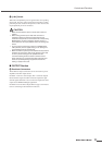
@ MEMORY [A] – [D] Buttons
• Recalling Memories
To recall a memory press and hold one of the MEMORY
buttons for about 2 seconds – the button’s indicator will
light and the mix settings assigned to that memory will be
recalled.
Settings are stored in the IMX644 memories via the
IMX644 Manager application. Memories A through D all
contain the same settings when the unit is initially shipped
from the factory.
• Switching Modes
To start the unit in IMX644 Manager mode, hold the MEM-
ORY [D] button while turning the [POWER] switch ON.
The unit starts up in the “normal” mode if the power is
turned on while the MEMORY [D] button is not held.
# [POWER] Switch & Indicator
Turns power to the unit ON or OFF. The indicator lights green
when the power is ON.
NOTE
• Since the level settings for each channel are stored in the
IMX644 unit itself, be sure that the IMX644 Manager applica-
tion is online when setting up the memories.
IMX644
Manager Mode
This mode allows communication with
the IMX644 application. Communica-
tion with AMX and similar external
controllers cannot occur in this mode.
Normal Mode
This is the unit’s normal operating
mode. Communication with AMX and
similar external controllers is also pos-
sible in this mode. Communication
with the IMX644 Manager application
is not possible in this mode.