


Appendix
22 IMX644 Owner’s Manual
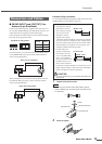
Output impedance of signal generator : 150 ohms
Frequency Response
20Hz-20kHz, reference to the nominal output level @1kHz
Total Harmonic Distortion
@1kHz
*Total Harmonic Distortion are measured with a 22kHz low pass filter
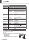
EIN (EIN=Equivalent Input Noise)
* EIN are measured with a IHF-A filter
Hum & Noise
* Hum & Noise are measured with a DIN AUDIO filter
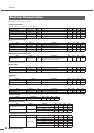
Crosstalk
@1kHz
Maximum voltage gain
@1kHz
Phantom Voltage
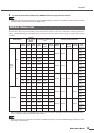
Indicator turn on level
Level Meter turn on level
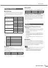
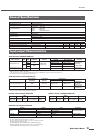
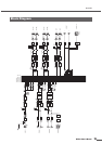
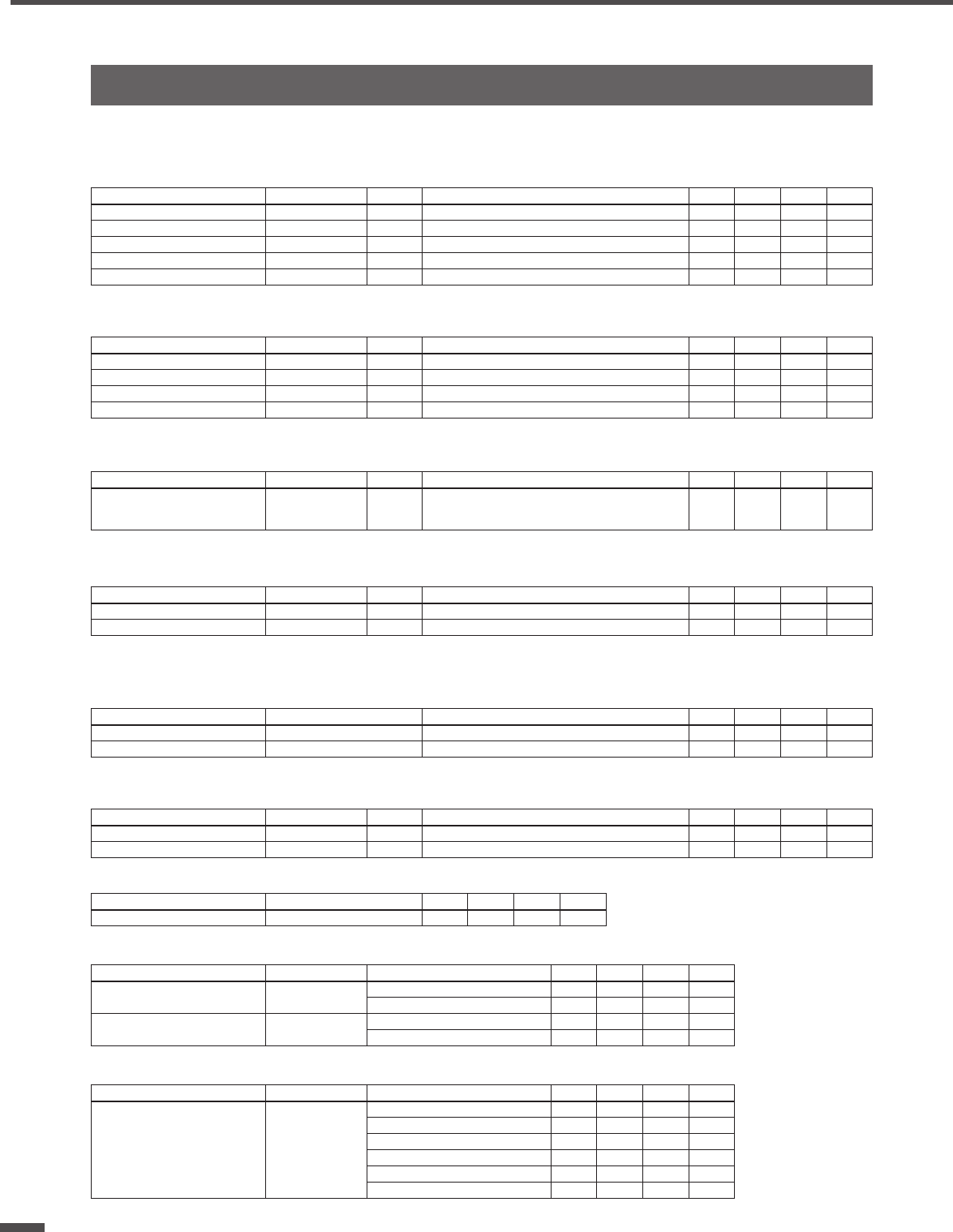
Electrical Characteristics
Input Output RL Conditions Min. Typ. Max. Unit
MONO INPUT [1-6] OUTPUT [1-4] 10KΩ – -1.5 0.0 0.5 dB
STEREO INPUT [1L/R-4L/R] OUTPUT [1-4] 10KΩ –-10.0 0.5 dB
STEREO INPUT [1L/R-4L/R] REC OUT [L, R] 10KΩ –-10.0 0.5 dB
OPTICAL IN OUTPUT [1-4] 10KΩ –-10.0 0.5 dB
OPTICAL IN REC OUT [L, R] 10KΩ –-10.0 0.5 dB
Input Output RL Conditions Min. Typ. Max. Unit
MONO INPUT [1-6] OUTPUT [1-4] 10KΩ +4dBu@1kHz, GAIN: MAX, PAD: OFF – – 0.1 %
MONO INPUT [1-6] OUTPUT [1-4] 10KΩ +4dBu@1kHz, GAIN: MIN, PAD: ON – – 0.08 %
STEREO INPUT [1L/R-4L/R] OUTPUT [1-4] 10KΩ +4dBu@1kHz – – 0.1 %
STEREO INPUT [1L/R-4L/R] REC OUT [L, R] 10KΩ -4dBV@1kHz – – 0.1 %
Input Output RL Conditions Min. Typ. Max. Unit
MONO INPUT [1-6] OUTPUT [1-4] 10KΩ
Rs=150Ω, GAIN:MAX, PAD: OFF
OUTPUT level control at nominal level and one
INPUT level control at nominal level.
––-120 dBu
Input Output RL Conditions Min. Typ. Max. Unit
– OUTPUT [1-4] 10KΩ all level control at minimum level – – -82 dBu
– REC OUT [L, R] 10KΩ all level control at minimum level – – -90 dBV
from/to to/from Conditions Min. Typ. Max. Unit
CH N CH (N-1) or (N+1) all adjacent inputs – – -70 dB
CH N CH (N-1) or (N+1) all adjacent outputs – – -70 dB
Input Output RL Conditions Min. Typ. Max. Unit
MONO INPUT [1-6] OUTPUT [1-4] 10KΩ Rs=150Ω, GAIN: MAX, PAD: OFF – 58 – dB
MONO INPUT [1-6] REC OUT [L, R] 10KΩ Rs=150Ω, GAIN: MAX, PAD: OFF – 52.2 – dB
Output Conditions Min. Typ. Max. Unit
MONO INPUT [1-6] hot & cold: No load 46 48 50 V
Input Output Conditions Min. Typ. Max. Unit
MONO INPUT [1-6]
STEREO INPUT [1L/R-4L/R]
–
PEAK red LED: ON -4 -2 0 dBFs
SIGNAL green LED: ON -42 -38 -34 dBFs
– OUTPUT [3, 4]
PEAK red LED: ON -4 -2 0 dBFs
SIGNAL green LED: ON -48 -44 -40 dBFs
Input Output Conditions Min. Typ. Max. Unit
– OUTPUT [1,2]
PEAK red LED: ON -4 -2 0 dBFs
-8 orange LED: ON -10 -8 -6 dBFs
-14 orange LED: ON -16 -14 -12 dBFs
-20 green LED: ON -22 -20 -18 dBFs
-32 green LED: ON -34 -32 -30 dBFs
-44 green LED: ON -48 -44 -40 dBFs