


IMX644 Owner’s Manual 15
Mix Functions
The IMX644 mix functions can be programmed and edited in detail using the IMX644 Manager installed on a computer (page 7). The
mix functions that can be controlled by the IMX644 Manager application are discussed in this section. For operating details refer to the
IMX644 Manager Owner’s Manual.
To enable communication with the IMX644 Manager application, press and hold the IMX644 MEMORY [D] button while turning the
[POWER] switch ON.
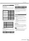
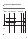
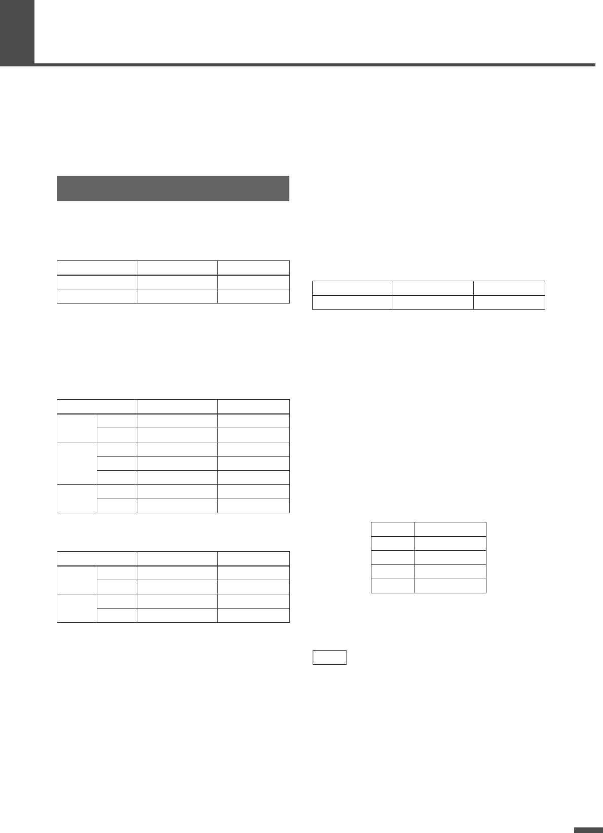
■ GAIN
The gain of the mono input channel head amplifiers can be indi-
vidually adjusted and displayed.
■ INPUT EQ
The parameters of the input channel equalizers can be individu-
ally adjusted and displayed. The parameters available for each
channel are listed below.
MONO INPUT CHANNEL
STEREO INPUT CHANNEL
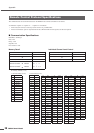
■ MATRIX
The MATRIX allows individual input channels to be assigned to
any of the mixer’s output channels. The assignments are shown
on the display. The initial default settings are: send assignments
to all output channels are ON, with only OUT1 assigned to the
REC OUT channel. The send levels from individual mono input
channels to the output channels can also be adjusted and dis-
played.
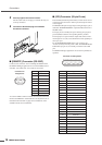
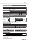
■ Temporary Matrix Assignment
Changes
The panel controls can be used to temporarily turn on the output
assignments of individual input channels, as follows.
1 Set all OUTPUT channel level controls to “0”.
2 Set the level of the INPUT channel to be
assigned to “10”.
3 Press and hold the MEMORY button correspond-
ing to the output channel you want to assign the
input channel to for longer than 3 seconds while
rotating the INPUT channel level control towards
“0”.
4 The corresponding MATRIX indicator will light.
5 Repeat for other channels as required.
NOTE
• Output assignments made in this way are only temporary and
will not be saved to memory. If power to the unit is turned
OFF and then ON again the memorized settings prior to
making the changes as described above will be recalled.
Input Channels
Parameter Range Initial value
GAIN (PAD is off) -54dB – -30dB -35dB
GAIN (PAD is ON) -20dB – +4dB -1dB
Parameter Range Initial value
HIGH
G -15dB – +15dB 0dB
F 2kHz – 18kHz 10kHz
MID
G -15dB – +15dB 0dB
F 40Hz – 18kHz 2kHz
Q 0.5 – 12.0 0.7
LOW
G -15dB – +15dB 0dB
F 40Hz – 2kHz 100Hz
Parameter Range Initial value
HIGH
G -15dB – +15dB 0dB
F 2kHz – 18kHz 10kHz
LOW
G -15dB – +15dB 0dB
F 40Hz – 2kHz 100Hz
Parameter Range Initial value
SEND LEVEL -∞ – 0dB 0dB
Button Output channel
A OUTPUT 1
B OUTPUT 2
C OUTPUT 3
D OUTPUT 4