


20
English
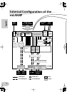
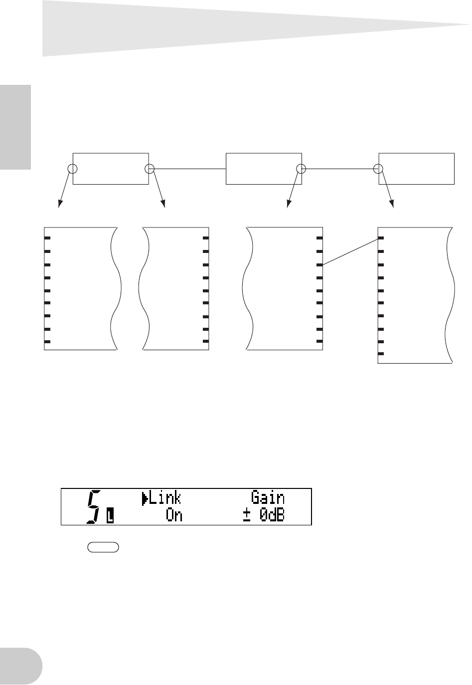
Routing I/O signals between
mLAN devices
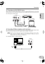
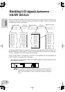
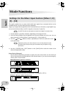
After connecting the mLAN8P to each device via cables, you can easily route and connect I/O sig-
nals between the devices without re-patching the cables. An operation common to both input
and output connections is performed.
The diagram above illustrates an example of routing the output signal from audio channel 3 on a
Yamaha A5000 (B) to audio channel 1 (Input 1) on the mLAN8P. Each device has a nickname,
“Detroit,” “Liverpool,” and “Hamamatsu” from left to right.
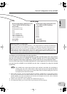
Follow the steps below to configure this connection on the mLAN8P. For more information on
other connections, refer to the notes in the steps.
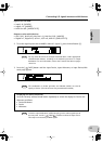
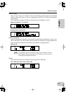
1. Press [MIXER 1] to enter MIXER 1 mode. The mLAN8P displays the channel parameter in the
mode previously selected.
For any cases other than the example described above, select one of the fol-
lowing modes, according to the desired mLAN input source or output desti-
nation. For more information, refer to the Function Tree table on pages 18
and 19.
mLAN output plugmLAN output plug
mLAN input plugmLAN input plug
IEEE1394
standard cable
IEEE1394
standard cable
YAMAHA mLAN8P
YAMAHA A5000 YAMAHA A5000
audio 1ch
audio 2ch
audio 3ch
audio 4ch
audio 5ch
audio 6ch
audio 7ch
audio 8ch
MIDI
audio 1ch
audio 2ch
audio 3ch
audio 4ch
audio 5ch
audio 6ch
audio 7ch
audio 8ch
MIDI A
MIDI B
audio 1ch
audio 2ch
audio 3ch
audio 4ch
audio 5ch
audio 6ch
audio 7ch
audio 8ch
MIDI
audio 1ch
audio 2ch
audio 3ch
audio 4ch
audio 5ch
audio 6ch
audio 7ch
audio 8ch
MIDI
(A) (B)
Liverpool HamamatsuDetroit
NOTE