


162
Appendix/Anhang/Annexe
● ● ● ● ● ● ● ● ● ● ● ● ● ● ● ● ● ● ● ● ● ● ● ● ● ● ● ● ● ● ● ● ● ● ●
Installing Options/Installationsoptionen/Installation des options
c
-2
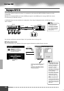
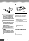
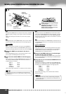
Install the first SIMM in the rear slot (the slot closest to the PSR-
9000 rear panel), inserting it at an angle as shown in the illustra-
tion.
Make sure that the parts at locations A, B, and C are properly
aligned.
c
-3
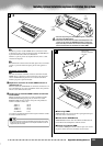
Holding both edges of the SIMM module, raise it to the vertical
position until it is firmly clamped by the left and right stoppers.
Second SIMM
c
-4
After confirming the orientation, insert the second SIMM into
the front slot (the slot closest to the PSR-9000 keyboard), and
raise it to the vertical position in the same way as the first SIMM.
v
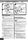
Replace the SIMM cover and attach it with the six
screws.
Set the PSR-9000 right-side up, and connect the power cord to
the rear-panel AC INLET jack and an AC outlet.
b
Check that the installed SIMMs are functioning prop-
erly.
Turn on the power, go to the SAMPLING display (page 41), and
check that the REMAIN TIME value matches the amount of
installed memory, as follows:
4MB x 2 106.9s
8MB x 2 202.1s
16MB x 2 392.3s
32MB x 2 772.7s
No SIMMS 11.8s
(These values apply when there is no data in the wave memory.)
• Although the wave memory of the PSR-9000 can be expanded to 65
megabytes, the maximum size of a single sample recording is 32 mega-
bytes (380 sec.).
c
-2
Installieren Sie das erste SIMM-Modul in den hinteren Steck-
platz (den der PSR-9000 Rückseite nächsten Schlitz), und stek-
ken Sie es in einem Winkel ein, wie in der Abbildung gezeigt.
Vergewissern Sie sich, daß die Teile an den Punkten A, B und C
richtig ausgerichtet sind.
c
-3
Halten Sie beide Kanten des SIMM-Moduls, und heben Sie es in
eine senkrechte Position, bis es von der linken und rechten Feder
festgeklemmt ist.
Zweites SIMM-Modul
c
-4
Nach dem Überprüfen der Ausrichtung stecken Sie das zweite
SIMM-Modul in den vorderen Steckplatz (den der PSR-9000
Tastatur nächsten Schlitz), und heben Sie es wie das erste
SIMM-Modul in die senkrechte Position.
v
Setzen Sie die SIMM-Abdeckung auf, und befestigen
Sie diese mit den sechs Schrauben.
Stellen Sie das PSR-9000 wieder richtig herum auf, und schlie-
ßen Sie das Netzkabel mit der rückseitigen AC INLET-Buchse
und einer Steckdose an.
b
Überprüfen Sie, ob die installierten SIMM-Module rich-
tig funktionieren.
Schalten Sie das Gerät an, wechseln Sie zum SAMPLING-Dis-
play (Seite 41) und überprüfen Sie, ob der REMAIN TIME-Wert
der Menge des installierten Speichers wie folgt entspricht:
4 MB x 2 106.9s
8 MB x 2 202.1s
16 MB x 2 392.3s
32 MB x 2 772.7s
No SIMMS 11.8s
(Diese Werte sind richtig, wenn sich keine Daten im Wave-
Memory befinden)
• Die maximale Größe eines einzelnen Samples beträgt 32 Megabyte,
obwohl der Wave-Speicher des PSR-9000 bis auf 65 MB (380 Sek.) auf-
gerüstet werden kann.
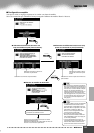
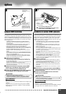
3 -2
• Make sure that the entire length of the SIMM
is evenly inserted.
• Stellen Sie sicher, daß die ganze Länge des
SIMM-Moduls gleichmäßig
• Veillez à ce que le module soit inséré unifor-
mément sur toute sa longueur.
C
B
A
• Lug
• Feder
• Tenon
• Lug
• Feder
• Tenon
• SIMM hole
• SIMM-Loch
• Fente de SIMM
• Slot protrusion
• Slot protrusion
• Saillie de connecteur
• SIMM hole
• SIMM-Loch
• Fente de SIMM
• SIMM notch
• SIMM-Kerbe
• Encoche de SIMM
472