


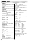
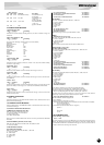

MIDI Data Format
41
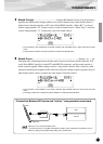
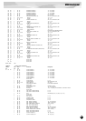
RPN Data-entry
LSB MSB MSB parameter Data Range
00H 00H mmH Pitch Bend Sensitivity mm:00H-18H (0-+24)
Default:02H
01H 00H mmH Fine Tune mm:00H-40H-7FH
(-64-0-+63)
Default : 40H 00H
02H 00H mmH Coarse Tune mm:28H-40H-58H
(-24-0-+24)
Default : 40H 00H
7FH 7FH — Null —
5. CHANNEL MODE MESSAGES
<All Sounds Off> 78H
Cntrl# parameter Data Range
120 ———— 0
Terminates all sounds currently sounding. However, the status of channel messages are
maintained.
<Reset All Controllers> 79H
Cntrl# parameter Data Range
121 ———— 0
The values of the following controllers will be reset to the defaults.
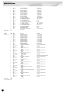
Pitch Bend Center
Channel Aftertouch 0
Modulation 0
Breath Control Max
Foot Control Max
Expression Max
Control Change 13 Center
Hold 1 Off
Portamento Off
Soft Pedal Off
RPN Null
<All Notes Off> 7BH
Cntrl# parameter Data Range
123 ———— 0
Terminates all notes currently on. However, if Hold 1 is on, notes will continue sounding
for the time set previously.
<Omni Off> 7CH
Cntrl# parameter Data Range
124 ———— 0
Performs the same function as when an All Notes Off message is received.
<Omni On> 7DH
Cntrl# parameter Data Range
125 ———— 0
Performs the same function as when an All Notes Off message is received. It will not acti-
vate OMNI ON.
<Mono> 7EH
Cntrl# parameter Data Range
126 Mono 0...16
Performs the same function as when an All Sounds Off message is received, and if the 3rd
byte (mono number) is in the range of 0 - 16, and sets the instrument to Mono Mode.
<Poly> 7FH
Cntrl# parameter Data Range
127 ———— 0
Performs the same function as when an All Sounds Off message is received, and sets the
instrument to Poly mode.
6. CHANNEL AFTERTOUCH
Status: DnH
If the Part Parameter Rcv CHANNEL AFTER TOUCH = OFF, that Part will not receive
Channel After Touch Messages.
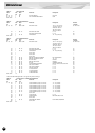
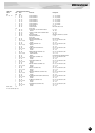
7. SYSTEM EXCLUSIVE MESSAGES
If the Part Parameter Rcv SYSTEM EXCLUSIVE = OFF, that Part will not receive Sys-
tem Exclusive Messages.
<UNIVERSAL REALTIME MESSAGES>
1)MIDI Master Volume(receive only)
F0H, 7FH, xnH, 04H, 01H, llH, mmH, F7H
xn : n=Device Number, xn=7F : Broadcast
ll : Master Volume LSB
mm : Master Volume MSB
When received, the Volume MSB will be effective for the System Parameter MASTER
VOLUME.
2)General MIDI System On (receive only)
F0H, 7EH, 7FH, 09H, 01H,F7H or F0H, 7EH, xnH, 09H, 01H, F7H
xn : n=Device Number
<PARAMETER CHANGE>
[VL70-m Native Format]
F0H, 43H, 1nH, 57H, ahH, amH, alH, ddH, ~, ddH, F7H
1n : n=Device Number
ah : Address High
am : Address Mid
al : Address Low
dd : Data
1) VL System Parameters See <Table 3>
2) Current Voice / Common Misc Parameters See <Table 4>
3) VL Part Parameters See <Table 6>
4) Current Voice / Element Parameters See <Table 8>
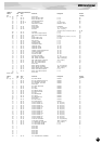
[XG Format]
F0H, 43H, 1nH, 4CH, ahH, amH, alH, ddH, ~, ddH, F7H
1n : n=Device Number
ah : Address High
am : Address Mid
al : Address Low
dd : Data
1) XG System On(receive only) See <Table 1>
2) XG System Parameters See <Table 2>
3) Multi Part Parameters See <Table 3>
When this message is sent, the preset Part Number is used.
[Other]
1) MIDI Master Tune(receive only)
F0H, 43H, 1nH, 27H, 30H, 00H, 00H, mmH, llH, ccH, F7H
1n : n=Device Number
mm : Master Tune MSB
ll : Master Tune LSB
cc : Don’t care
When received, the System Parameter will reflect the Master Tune.
<BULK DUMP> (receive only)
[VL70-m Native Format]
F0H, 43H, 0nH, 57H, bmH, blH, ahH, amH, alH, ddH, ~, ddH, ccH, F7H
0n : n=Device Number
bm : Byte Count MSB
bl : Byte Count LSB
ah : Address High
am : Address Mid
al : Address Low
dd : Data
cc : Check Sum
1) VL System Parameters See <Table 3>
2) Current Voice / Common Misc Parameters See <Table 4>
3) VL Part Parameters See <Table 6>
4) Current Voice / Element Parameters See <Table 8>
5) Custom Voice Parameters See <Table 9>
6) Internal Voice Parameters See <Table 10>
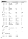
[XG Format]
F0H, 43H, 0nH, 4CH, bmH, blH, ahH, amH, alH, ddH, ~, ddH, ccH, F7H
0n : n=Device Number
bm : Byte Count MSB
bl : Byte Count LSB
ah : Address High
am : Address Mid
al : Address Low
dd : Data
cc : Check Sum
1) XG System Parameters See <Table 2>
2) Multi Part Parameters See <Table 5>
For the Address and Byte Count, refer to the supplementary tables.
Here, the Byte Count is indicated by the “TOTAL SIZE” in the table.
The block’s leading byte is the Bulk Dump and Dump Request’s Address.
A “Block” is the lumped together unit which is bound by the “Total Size”.
The Check Sum is the value that results in a value of 0 for the lower 7 bits when the
Address, Byte Count, Data, plus the Check Sum itself are added.
3) Part Assign (MIDI Parameter Change) See <Table 7>
F0H 43H 1nH 4CH 70H nnH ssH ppH F7H
n: Device Number
nn: Plug-in Board Type (PLG150-VL is "00.")
ss: Serial Number (which identifies the PLG boards when two same boards are installed)
00: for first PLG150-VL
01: for second PLG150-VL
pp: Part Number (to which the PLG150-VL is assigned.)
00: Part 1
.
.
0F: Part 16
7F: off
8. REALTIME MESSAGES
<Active Sensing> (receive only)
Status: FEH
Once Active Sensing is received, if no MIDI data is received for longer than an interval of
300msec, the instrument will perform the same function as when ALL SOUND OFF and
ALL NOTE OFF, RESET ALL CONTROLLER messages are received, and will return to
the status in which Active Sensing is not monitored.