2
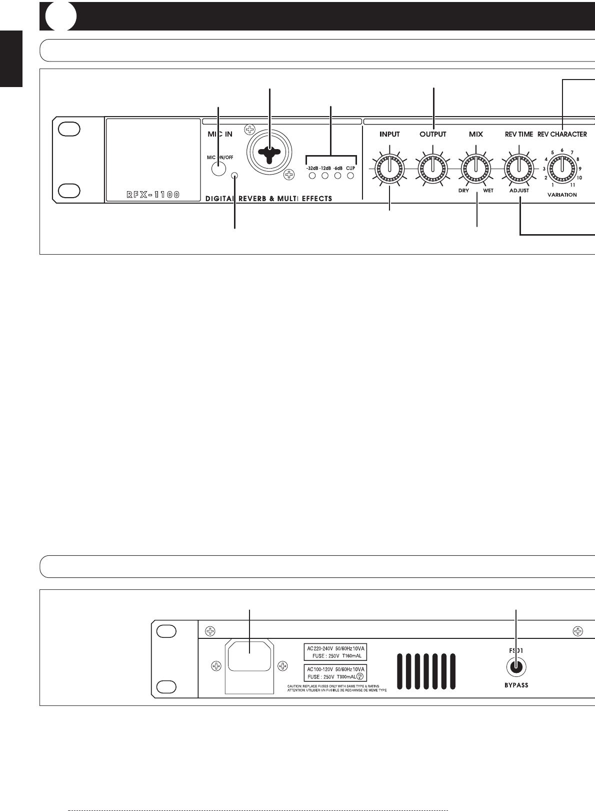
(1) MIC IN connector
A dynamic microphone with an impedance of about
600 ohms can be connected here, for use as an
additional input source. Either an XLR plug (balanced
connection) or a phone plug (balanced/unbalanced
connection) can be used.
Normally the input signal from this connector is
mixed with the signal from the rear-panel INPUT
jacks. When the VOCODER effect is selected, the
signal from this connector serves for controlling the
sound character and the envelope (volume change
curve) of the VOCODER effect.
(2) MIC ON/OFF switch
This switch turns the signal from the MIC IN
connector on and off.
* Before inserting or removing the plug of a
microphone into and from the MIC IN connector, be
sure to set the MIC ON/OFF switch to OFF.
(3) MIC IN indicator
When the MIC ON/OFF switch is ON, this indicator
lights up.
(4) Level meter
These indicators show the signal input level.
(5) INPUT control
Serves to adjust the signal from the INPUT jacks and
the MIC IN jack.
(6) OUTPUT control
Serves to adjust the level of the signal supplied at the
OUTPUT jacks.
(7) MIX control
Serves to adjust the balance between original sound
(DRY) and effect sound (WET). When the control is
turned fully counterclockwise, only the original sound
is output. When the control is turned fully clockwise,
only the effect sound is output.
ZOOM RFX-1100
Controls and Functions
Front Panel
Rear Panel
(1) MIC IN connector
(2) MIC ON/OFF switch
(4) Level meter
(5) INPUT control
(6) OUTPUT control
(7) MIX control
(3) MIC IN indicator
(2) BYPASS jack
(1) POWER connector
(1) POWER connector
The supplied power cable is to be connected here for
powering the unit.
(2) BYPASS jack
Serves for connection of the foot switch FS01 (option)
for switching effects on and off.
Controls and Functions


