System and Control Options
45
9.2 Setup System - Overview
The Setup System screen displays seven options that allow you to configure input and output
devices and their relationships, the common alarm, the modem, pagers to be dialed when alarms
occur, and a variety of system details, such as login password and system date and time:
• Setup Input
• Setup Common Alarm
• Setup Sensor
•Setup I/O Matrix
• Setup Output
• Setup Modem & Pagers
• Setup System Info
• Setup Exp Board
9.3 Setup System - Setup Input
The Universal Monitor has eight digital input points that may be
configured individually. If the optional Expansion Board is used, an
additional 16 digital inputs may also be configured. These inputs may
have a wide variety of Liebert or other manufacturers’ equipment
connected for monitoring.
To configure a digital input:
Log In and Choose Setup System
• From the Main Menu, use the arrows
↑↓ to choose System and
Control, then press Enter ↵ (see 9.1 - Login for help).
• Enter your password at the Login screen.
• From the System and Control Menu, use the arrows
↑↓ to choose
Setup System, then press Enter ↵ .
Select a Digital Input to Configure
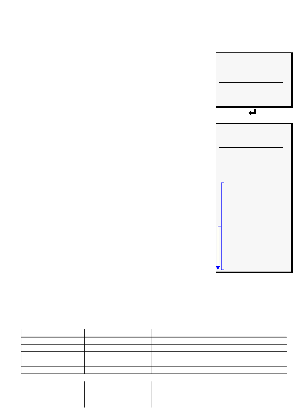
• From the Setup System Menu, shown at right, use the arrows
↑↓ to
choose Setup Input and press Enter ↵ .
• From the Select Input Menu, choose the input you want—for exam-
ple, Input_01—and press Enter ↵ .
Table 21 shows the digital input features you may change, along with
the default settings: you may change the name of the input, define it as
normally open or closed, and specify it as alarmable or as an event.
• Alarmable inputs may be defined as either Unlatched or Latched.
• Event status allows you to monitor a digital input’s state—and use a change in state to initiate an
action through an output, if desired—without triggering an alarm. Events are always Unlatched.
• You may also specify a time delay before the Universal Monitor responds to an alarm or event.
Use the steps following Table 21 to change the default settings for any digital input.
Table 21 Default settings - digital inputs
Feature Default Other Options
LABEL INPUT_01 Any name (up to eight characters)
NORM OPEN/CLOSE NO (Normally open) NC (Normally closed)
ALARM/EVENT AL (Alarmable) EV (Event)
LATCHED NL (Unlatched) / N (No)* L (Latched) / Y (Yes)*
DELAY 00:01 (1 second) Any time (in minutes and seconds) from 00:00 to 99:59
* NOTE: Different abbreviations are used to designate a digital input as Latched or Unlatched as shown below.
Settings - Select Input Menu
(see Section 9.3)
When configuring an input
(see Section 9.3.4)
Unlatched NL (Not Latched) N (No, not latched)
Latched L (Latched) Y (Yes, latched)
Setup System Menu
> SETUP INPUT
SETUP COMMON ALARM
SETUP SENSOR
SETUP I/O MATRIX
↑↓=NEXT ↵ =SELECT
SETUP OUTPUT
SETUP MODEM&PAGERS
SETUP SYSTEM INFO
SETUP EXP BOARD
Select Input Menu
SELECT INPUT
> INPUT_01 NO-AL-NL
INPUT_02 NO-AL-NL
↑↓=NEXT ↵=SELECT
INPUT_03 NO-AL-NL
INPUT_04 NO-AL-NL
INPUT_05 NO-AL-NL
INPUT_06 NO-AL-NL
INPUT_07 NO-AL-NL
INPUT_08 NO-AL-NL
INPUT_09 NO-AL-NL
INPUT_10 NO-AL-NL
INPUT_11 NO-AL-NL
INPUT_12 NO-AL-NL
INPUT_13 NO-AL-NL
INPUT_14 NO-AL-NL
INPUT_15 NO-AL-NL
INPUT_16 NO-AL-NL
INPUT_17 NO-AL-NL
INPUT_18 NO-AL-NL
INPUT_19 NO-AL-NL
INPUT_20 NO-AL-NL
INPUT_21 NO-AL-NL
INPUT_22 NO-AL-NL
INPUT_23 NO-AL-NL
INPUT_24 NO-AL-NL
NOTE: INPUT_09 - INPUT_24
for optional Expansion Board
