60 Chapter 3
Performance Tests
Conversion Loss and Frequency Response
Performance Tests
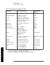
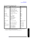
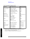
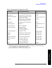
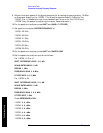
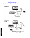
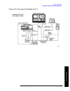
9. Adjust the output power of the signal generator for a reading of approximately -10 dBm
on the power meter for the 11970K, V or W and for approximately -3 dBm for the
11970A, Q or U. (Make sure that the unleveled light is not on for the 11970V and
11970W. Vary the power by adjusting the rotary vane attenuator.)
10.On the spectrum analyzer, press
SHIFT and [MKR/∆ ⇑ STP SIZE].
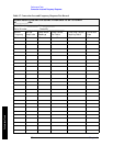
11.Set spectrum analyzer
CENTER FREQUENCY to:
11970K: 22 GHz
11970A: 33 GHz
11970Q: 41 GHz
11970U: 50 GHz
11970V: 62 GHz
11970W: 92 GHz
12.On the spectrum analyzer, press
SHIFT and SWEEP, CONT.
13.Set the spectrum analyzer controls as follows:
For 11970K, A, Q or U:
SHIFT, REFERENCE LEVEL, 3, 0, -dB
SCALE
ENTER dB/DIV, 2, dB
RES BW
, 1, MHz
FREQUENCY SPAN, 2, 0, MHz
CF STEP SIZE
, 5, 0, 0, MHz
For 11970V or W:
SHIFT, REFERENCE LEVEL, 3, 0, -dB
SCALE
ENTER dB/DIV, 2, dB
RES BW
, 3, MHz
FREQUENCY SPAN, 2, 0, 0, MHz
CF STEP SIZE
, 1, GHz
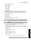
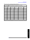
Press REFERENCE LEVEL:
11970K:
3, 6, -dBm
11970A: 3, 8, -dBm
11970Q: 4, 0, -dBm
11970U: 4, 0, -dBm
11970V: 4, 8, -dBm
11970W: 5, 6, -dBm


