


Chapter 3 61
Performance Tests
Conversion Loss and Frequency Response
Performance Tests
Then press CENTER FREQUENCY:
11970K:
1, 8, GHz
11970A: 2, 6, [.] 5, GHz
11970Q: 3, 3, GHz
11970U: 4, 0, GHz
11970V: 5, 0, GHz
11970W: 7, 5, GHz
14.Press MARKER, PEAK SEARCH. If necessary, press MKR→CF and use DISPLAY LINE
ENTER to find the average of the signal’s peak variations. (When testing 11970V or
11970W mixers, it is important to re-zero the power meter for each measurement.)
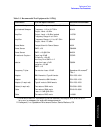
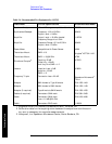
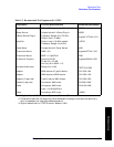
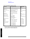
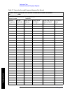
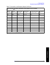
15.Record the following in Table 3-7:
Marker Frequency
Marker Amplitude
Power Meter Reading
Power Sensor Cal Factor or Correction Factor (dB)
Directional Coupler Coupling Factor
NOTE For the purposes of this measurement, the directional coupler coupling factor
is defined as the ratio of the power at the output flange to the power at the
coupled flange.
16.Calculate the conversion loss of the mixer with the following equation:
Conversion Loss = Power Meter Reading - 10 log(Cal Factor) - Spectrum Analyzer
Marker Amplitude - Coupling Factor
(or given the Power Meter Correction Factor in dB: Conversion Loss = Power Meter
Reading + Power Meter Correction Factor - Spectrum Analyzer Marker Amplitude -
Coupling Factor)
For example:
Power Meter Reading = -10.03 dBm
Cal Factor = 94.8%
or Correction Factor = -0.232 dB
Spectrum Analyzer reading = -39.78 dBm
Coupling Factor 8.93 dB
then:
Conversion Loss (-10.03) - 10 log(.948) - (-39.78 dBm) - 8.93 dB = 21.05 dB