


Chapter 3 63
Performance Tests
Conversion Loss and Frequency Response
Performance Tests
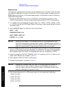
NOTE The conversion loss indicated on the mixer calibration label includes the loss
in the IF cable. If other than the specified cable is used, then the loss in that
cable must be compensated for when making amplitude measurements.
18.Increment the frequency of the signal generator 500 MHz higher.
19.Press DATA [
↑], then PEAK SEARCH and MKR→CF on the spectrum analyzer.
20.Repeat steps 15 through 18 until the appropriate frequency listed below is reached.
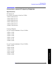
11970K: 26.5 GHz
11970A: 40.0 GHz
11970Q: 50.0 GHz
1197OU: 60.0 GHz
11970V: 75.0 GHz
11970W: 110.0 GHz
21.Repeat steps 1 through 19 for LO inputs to the mixer of 14.5 dBm, 16.0 dBm, and
18.0 dBm. In step 5, measure each of these levels at the end of the cable normally
connected to the mixer LO input.
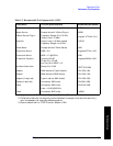
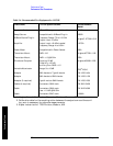
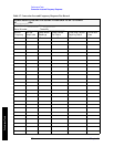
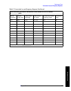
22.Frequency response is the difference between the maximum and minimum conversion
losses recorded in Table 3-7. For LO power levels between 14.5 and 16.0 dBm this
difference must be less than:
3.8 dB (for 11970K, 11970A, 11970Q or 1197OU)
4.2 dB (for 11970V)
6.0 dB (for 11970W)
• For LO power levels between 14.0 and 18.0 dBm, the difference must be less than:
5.6 dB (for 11970K, 11970A, 11970Q, 11970U or 11970V)
8.0 dB (for 11970W)
23.Maximum conversion loss must not exceed the following limits:
For an LO input power between 14.0 and 18.0 dBm.
11970K: 24 dB
11970A: 26 dB
11970Q: 28 dB
11970U: 28 dB
11970V: 40 dB
11970W: 46 dB