


17 U-CONTROL UMA25S User Manual
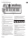
Pitch bend5.5.5
The Pitch Bend wheel E17 on the UMA25S is used to change the pitch of a note.
It has its own type of message in the MIDI specication.
The Pitch Wheel message can also be assigned to other continuous elements
(such as slider, knobs and expression pedal). This message has its own status
byte, so that it is only possible to adjust the MIDI channel (E10 rotary knob),
the range (E12 rotary knob) and the display (E16).
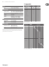
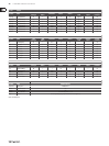
Table A.5 on the supplementary sheet gives you an overview of the ◊
rotary knob assignment in Edit Mode.
After-touch5.5.6
MIDI keyboards with after-touch are able to respond to pressure, even after the
key is hit, and to transmit this information. The function aects either specic
keys (Key Pressure) or all notes equally (Channel Pressure). The UMA25S keyboard
is not after-touch capable, but you can assign this function to other control
elements. This way you can control synthesizer parameters that are used to
control after-touch.
Normally, the key value “All” is selected. This setting makes after-touch equally
aect all played notes (“Channel Pressure”). In case you want to use the less
common polyphonic after-touch (“Key Pressure”), you can apply after-touch to
single keys by using the E11 rotary knob. However, since this is only supported
by very few sound generators, Channel Pressure usually does the job. For the
selected switch element, use E12 to determine the value at which after-touch
turns on and E13 to determine the value at which it turns o. This way you can
also use after-touch to adjust the modulation range (eect depth).
Table A.6 on the supplementary sheet gives you an overview of the ◊
rotary knob assignment in Edit Mode.
MIDI machine control (MMC)5.5.7
MIDI Machine Control allows you to operate the transport functions of a
sequencer or drum machine (for example, Start, Stop, Fast Forward and Rewind)
from the UMA25S.
The MIDI Machine Control functions are dedicated to the control push buttons
E1 – E8 (see Chapter 5.2.3) and are activated by pressing the MMC push
button (3). You can specify the MIDI device number of the unit supposed to
receive MMC data by using the E10 knob. For the Locate function, it is necessary
to specify the position. In order to do so, the Frame Rate you are using has to be
entered in Global Setup (Chapter 5.7).
Table A.7 on the supplementary sheet gives you an overview of the ◊
rotary knob assignment in Edit Mode.
GS/XG parameters5.5.8
GS/XG parameters belong to the category of CC and NRPN messages specied
in the MIDI standards GM (General MIDI), GS (Roland) and XG (Yamaha)
(see Table 7.1). These standards also include dedicated program numbers for
certain sounds. If you have a sound module that supports one of the standards,
assigning parameters is as easy as it gets.
The data have a similar structure to that of CC and NRPN messages. Use the
E11 rotary knob to select the most important GS/XG-compatible parameters,
which are shown on the display as (shortened) plain text (see Table 7.1).
Just like the CC messages, the value range can be adjusted with the rotary knobs
E12 (minimum value) and E13 (maximum value).
Table A.8 on the supplementary sheet gives you an overview of the ◊
rotary knob assignment in Edit Mode.
Using keys as control elements5.5.9
Not only the switch elements but also the keys on the keyboard can trigger
CC messages and Note messages. The advantage is that you don’t have to do
without the familiar feel of keys and velocity sensitivity. This means you have
25 more switch elements at your ngertips, with Note numbers that are freely
assignable (which is dierent to standard keyboard assignments). This is useful
when extracting individual drum sounds from a xed assignment (for example,
a General MIDI drum set) in order to map them to adjacent keys, even when the
sounds are octaves apart. Another option is to map the notes of a melody to
adjacent keys in order to play the melody literally in sequence.
Triggering Note messages with keys:
The data structure corresponds to that of the Note messages, except for the
Velocity, which can be played either with a x value (0 – 127) or with the Velocity
of the keyboard (E12 rotary knob). Turn E15 to discard the settings and return to
the normal assignment of the keyboard (Reset function; “reS” on display).
Triggering CC messages with keys:
The data structure corresponds to that of the CC messages for switching
elements, which can be played either with a x value (0 – 127) or with the
Velocity of the keyboard (E12 rotary knob). The switch behavior is determined
with E14. Turn E15 to discard the settings (“reS” on display).
Table A.9 on the supplementary sheet gives you an overview of the ◊
rotary knob assignment in Edit Mode.
Selecting multiple keys for the
Key Trigger function:
A special feature of the keyboard assignment lets you select multiple
keys at the same time. This helps you save time when assigning
messages, some of which are identical, or MIDI channels to dierent
keys. In a second step you can assign dierent MIDI channels,
Note values and Controller values to individual keys.
Press and hold down the EDIT/EXIT push button. The device 1.
switches to Edit Mode.
Press the keys that you want to edit one after another. You can 2.
either select consecutive keys or choose a range of the keyboard
with a sliding movement (glissando). It is also possible to select
single, non-consecutive keys. The Note numbers you choose are
now shown on the display in the order in which they are pressed.
Release the EDIT/EXIT push button.3.
With the rotary knobs, you can carry out the assignment of the 4.
MIDI messages for the selected keys.
Press the ENTER key to conrm.5.
Save the assignments as preset.6.