


9 U-CONTROL UMA25S User Manual
Controls and Connections3.
(9)
(5)
(6)
(3)
(4)
(2)
(10) (11) (12) (13)(8)(7)
(1)
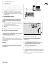
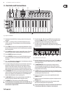
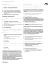
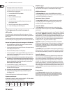
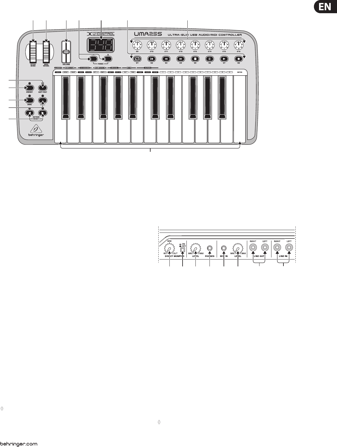
Fig. 3.1: Top view of the UMA25S
The keyboard of the UMA25S has 25 velocity-sensitive, full-size keys with (1)
half action.
The (2) OCT </> push buttons allow you to shift the keyboard range up to
4 octaves up or down. These push buttons are also used for trans position
(see Chapter 5.2.2).
Press the (3) MMC push button to use the default MMC (MIDI Machine Control)
functions of the control elements E1 to E8. The MMC functions are printed on
these control elements.
Press the (4) MUTE push button to suppress sending MIDI messages. This allows
you to move control elements without changing the parameter values.
Press the (5) PRESET push button to load a preset.
Press the (6) EDIT/EXIT push button once to switch to Edit Mode. By pressing
the button a second time, you exit Edit Mode without having accepted
any changes.
The –/+ push buttons let you select a preset. Press both buttons at the same (7)
time to silence stuck MIDI notes (PANIC).
The 3-digit LED display briey indicates the current rmware version when (8)
the keyboard is switched on, after which the selected preset number is
displayed. In Play Mode, the display shows the value changes in real time
when operating the control elements. In Edit Mode, the display shows the
MIDI commands, program and channel numbers as well as parameter values.
The (9) PITCH BEND wheel (E17) lets you change the pitch in real time. This way
a tone can be bent several semitones up or down while playing. The desired
pitch interval is adjusted on the controlled device. The PITCH BEND wheel
returns to the center position as soon as you let go of it.
The (10) MOD WHEEL (E18) works like a typical modulation wheel (MIDI CC 1).
When you let go of the modulation wheel, it keeps the set value.
The (11) VOLUME slider (E19) controls the volume (MIDI Controller 07).
The Pitch Bend wheel, the modulation wheel and the VOLUME slider are ◊
not restricted to their preconfigured functions, but can also have other
control functions assigned to them.
The push buttons (12) E1 – E8 can have any MIDI functions assigned to them.
By pressing the MMC push button (3) once, these push buttons use the
precongured transport control functions (see Chapter 5.5.7).
The 8 high-resolution rotary knobs (13) E9 – E16 generate Continuous
Controller messages. In Edit Mode, the rotary knobs can be assigned to any
controller number.
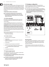
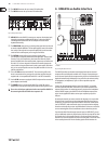
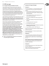
(14) (15) (16) (17) (18) (19) (20) (21)
Fig. 3.2: Audio connectors on the rear panel
If the Direct Monitor function is turned on (press switch (14) (15)), the MIX control
allows you to adjust the volume level balance between the recording signal
and the playback signal.
The (15) MONITOR ON/OFF switch activates the Direct Monitor function.
The recording signal found at the MIC or LINE input is fed to the output
connectors LINE OUT and PHONES in order to avoid latency and the resulting
timing problems while recording.
The (16) LEVEL control lets you adjust the volume level of the headphone signal.
Turn the control completely to the left before plugging in the headphones to
avoid damage due to high volume levels.
Plug the green headphone connector of the supplied headset into the (17)
PHONES connector.
Plug the red connector of the headset or any dynamic microphone into the (18)
MIC IN connector.
The (19) LEVEL control adjusts the input volume of the microphone signal.
Make sure the input signal does not clip (distortion).
To prevent unwanted noise, always be sure that the input volume level ◊
is turned down to MIN when a microphone is not being used.