


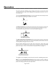


Simple Linking
Simple linking or “daisy-chaining” allows the expansion of mixer inputs in multiples of 8 inputs
by chaining together multiple mixers with auxiliary buses.To preserve certain mixer features,
this must be done in the way shown below. Follow these steps (see page 18 for jumper loca-
tions):
1. For each mixer, remove the jumper from J2 and place it on J1.This causes the Auxiliary
Out level to be set by an internal pot, fixing the linked gain structure.The external pot only
controls the headphone out level.
2. In the last mixer in the chain, remove the jumper from J18. Leave the jumper in place on
J17.This routes the AUX In to the Main output, preserving the Compressor/Limiter feature.
3.All other mixers in the chain should have jumper J18 in place, and J17 removed.
4. Connect each mixer’s AUX Out terminals with the AUX In terminals of the next mixer in
the chain.
5.Take the summed daisy-chain output from the Main Out terminals of the last mixer in the
daisy-chain.This must be the mixer with J17 in place (from step 2).
6.All mixers except the last mixer in the chain (#1 in the drawing below) must have all its
front panel M-A switches in the A position, to route its inputs to the auxiliary bus.The posi-
tion of jumpers J17 and J18 in the first mixer (#4 in the drawing below) do not matter, and
can be left undisturbed.
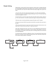
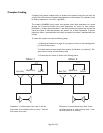
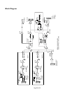
You should now have a daisy-chain configured as shown in the drawing below. Note that the
position of J17 and J18 are shown within the drawing of each mixer in the chain (except mixer
#4 in which the jumper position is immaterial).
Page 21 of 32
Aux Out
Main Out
Aux In
Mixer 1
Aux Out
Main Out
Aux In
Mixer 2
J18
J17
Aux Out
Main Out
Aux In
Mixer 3
J18
Aux Out
Main Out
Aux In
Mixer 4