


E-25
Assembly Instructions
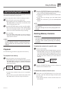
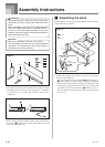
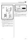
3.Rotate height adjustment screw 7 until it supports
crosspiece D, preventing the crosspiece from bending when
you press the pedals (Figure 5).
Important!
• Be sure to rotate adjustment screw 7 and perform the
adjustment procedure described above before
depressing the pedals. Failure to do so can result in
damage to crosspiece D.
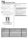
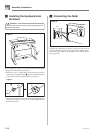
2.Attach back panel C to the 4 brackets and crosspiece D.
Note that the back panel C should be installed so it is in
front of the 4 brackets (Figure 4). Use the two I screws,
six F screws to secure the back panel in place (Figures 3
and 4). Note that you must also install the G clip at this
time as shown in the illustration.
• First, install the topmost I screws on the left and right
sides of the back panel C. Note that you should slip the
G clip onto the F screw at point 5 before you screw in
the F screw.
• The back panel C should rest on the feet of side uprights
A and B as indicated by 6 in the illustration. Press the
back panel C against crosspiece D while installing the
I screws.
Figure 4
5
4
6
F
C
F
G
I
I
AB
G
I
(Back)
Figure 5
7
420A-E-029A