


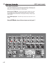

user options
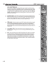
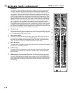
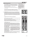
There are a number of user options available for the Stereo inputs. These are implemented by way of solder-pads on
the back-side of the Stereo Input circuit boards (upper EQ board of the pair). There are a number of solder-pads avail-
able, made up of split-circles of tinned copper. Solder is bridged (blobbed) across the 2 halves to complete the circuit and
implement the desired option. For the default setting, there is already a thin copper trace that connects the two halves,
completing the default connection. This existing trace MUST be cut (use an X-acto knife) before an option is implemented.
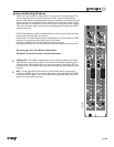
To change back to the default operation after an option was performed, remove the blobbed solder from the option
solder-pads (use a solder-sucker or solder-wick). Add a blob-link across the original, default pads to replace the thin trace
that was previously cut when the option was first performed.
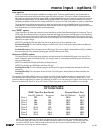
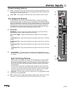
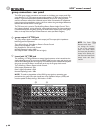
The specified Solder-Blob (SBXX) shown in the table should be linked (by solder-bridging) to complete the circuit
and implement the indicated option. The table below shows the specific SBXX for each of the 8 channels on a cir-
cuitboard. Before implementing an option (by blobbing), be SURE to cut the existing thin copper trace linking the two
halves of the default SB. Failure to do so will result in channel operation problems and possible circuit damage.
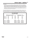
HPW Stereo Input
OPTIONS TABLE
“PRE” Feed For Aux Sends Channel Direct Out
Post-EQ (Default) Pre-Insert Pre EQ Post-EQ (Default) Pre-EQ
Chan-1 mono SB2 SB1 SB33 SB18 SB17
Chan-2 mono SB4 SB3 SB34 SB20 SB19
Chan-3 mono SB6 SB5 SB35 SB22 SB21
Chan-4 mono SB8 SB7 SB36 SB24 SB23
L/R L/R L/R L/R
Chan-5 stereo SB52/SB51 SB50/SB9 SB10/SB12 SB11/SB13
Chan-6 stereo SB28/SB29 SB26/SB27 SB14/SB16 SB15/SB25
Chan-7 stereo SB40/SB41 SB30/SB39 SB31/SB37 SB32/SB38
Chan-8 stereo SB44/SB45 SB42/SB43 SB46/SB48 SB47/SB49
5
p. 26
stereo input - options