


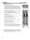
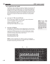
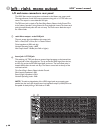
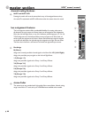

L/R and mono connectors- rear panel
The HPW Mono output connections are located on the Master rear output panel.
The output features a male XLR output connector, along with a 1/4” TRS Insert con-
nector. The output is a servo balanced XLR jack.
The TRS Insert jack is wired as Tip=Send, Ring=Return, Sleeve= Audio Ground. This
is the “industry-standard” wiring scheme for most single-jack inserts. The Insert send-
point is located directly after the main mix amp. The Insert return feeds the top of
the 100mm fader.
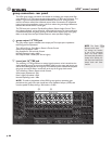
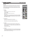
main Mono output - male XLR jack
The main output signal is available at this output jack.
Pin2 is +Drive, Pin3 is -Drive, Pin1 is Chassis Ground
Drive impedance is (50Ω each leg)
Nominal Operating Level= +4dBu
Max Output Level= +26dBu (into 2kΩ or higher)
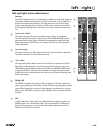
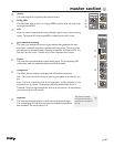
insert jack 1/4" TRS jack
This switching 1/4” TRS jack allows an external signal processor to be inserted into
the signal path of the main audio bus. The tip carries the SEND signal from the bus,
and the ring carries the RETURN signal back to the aux. The Insert-Send point is
located directly after the main mix amp. The Return comes back at the top of the
main level control.
Tip is Send, Ring is Return, Sleeve is Audio Ground.
Send (output) impedance is 50Ω
Return (input) impedance is 5KΩ
Nominal Operating Level= -2dBu
NOTE: To avoid any degradation of the HPW’s signal path, any processing gear
patched into the insert jack should have a low impedance output (<100Ω) and must
be capable of cleanly driving a 2KΩ load to +21dBu.
66
67
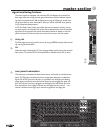
66 67
p. 38
HPW
TM
owner’s manual
left - right, mono output
9