


115
¡
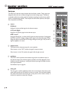
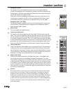
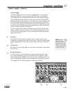
talkback section
The operator can use the built-in facilities of the HPW to talk to the main, group, or
aux buses in the console. Often times, the operator will need to selectively commu-
nicate with a performer, or slate a performance during a recording.
talkback input
This front-panel XLR jack can accept mic-level signals and is equipped with a phan-
tom power option header (internally located behind the XLR jack within the Master
module). The default setting for the phantom power is ON.
NOTE: +18 volts phantom power is available for the TB mic. Most condenser mics
will operate at this voltage, but there are some microphones that need the full, +48
volts to properly function. Only use dynamic microphones, or condensers that can
operate properly on +18 volts for the TB mic.
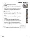
talkback level
This control sets the level of the TB signal to be sent to the selected buses.
talk to (talkback select switches)
The operator can choose which buses are fed by the Talkback audio using these 8
switches. The 3 main buses, all 8 groups, or the Aux buses (in pairs) can be selected.
talk on (talk back on with LED)
This latching switch feeds the Talkback audio to the selected buses. The LED lights
when it is active.
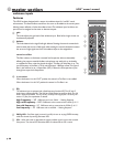
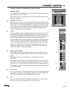
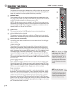
output metering
Ten dedicated LED meters show the output level of whatever signal is being con-
trolled by the corresponding 100mm fader. Normally the 8 Group outputs, along
with the L and R main buses are displayed across the 10 meters. If a Fader-Reverse
switch is depressed, that corresponding Aux output (1 thru 10) is displayed instead.
The displayed signal is Post-fader and Post-Mute. The meters have a VU-type
response, showing the average levels of the signals being monitored. Use the Peak
LEDs on each individual output to check for any overload conditions for that signal.
The nominal output level of the HPW console is +4dBu. This is indicated as 0 VU on
the meter scale.
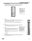
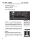
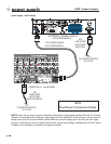
power supply monitor
These 4 LEDs, located above the Solo meters, monitor the internal voltages of the
Console. Each green LED indicates the presence of its indicated voltage rail. These
LEDs will illuminate when the Console is powered EITHER from its internal supply
OR from an external supply. See Power Supply section for further details.
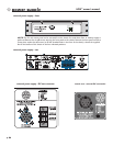
lamp connectors
A 12V DC BNC lamp connector is provided on each channel module for console
illumination. There are two lamp groups - one on each side of the master section.
These are current protected with fuses that automatically reset when an overload
condition is removed. (A severe overload may require power cycling to restore
lamp power.) A maximum of 750mA can be drawn from either group. This corre-
sponds to two high intensity Halogen bulbs, or four low intensity incandescent bulbs.
Gooseneck lamp assemblies are available separately.Positive voltage is on the center
pin. The connector barrel is at 0-volts.
NOTE: The +18 and -18
indicators are for the main
analog voltage rails. These are
used to power the majority of the
amps within the Console. The +12
indicator shows the aux-power rail
used to power the LEDs and other
non-audio circuits of the Console.
The +48 LED monitors the phantom
voltage.
+
NOTE: Any 12 volt acces-
sory can be powered from
these BNC connectors, as long as
it draws less than 750mA (total for
lamp group). You can try one of
those 12 volt personal fans to keep
cool when mixing on a hot day.
+
115
116
117
118
116
117
118
p. 52
HPW
TM
owner’s manual
master section