


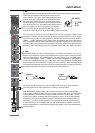
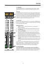

INPUT MONO
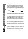
5. FX
The FX-controls are used to adjust individual amounts of the channel signals to be routed
to the FX1 and/or the FX2 unit. The split point of the “dry” signal is POST FADE or in other
words: the fader setting also infl uences the signal that is fed to the FX units.Before you
start to establish the effect mix, these controls should be set at their center position. From
this point you can increase or reduce the effect’s intensity, depending on your personal
preferences.Please monitor the PEAK LEDs in the FX1/2 channels during a performance.
The indicator should only light briefl y at the occurrence of high program peaks. If the indi-
cator is constantly lit, please lower the affected channels’ send levels at their FX controls.
For further information, please refer also to the paragraphs on the FX1/2 units.
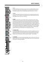
6. AUX
The AUX-control is primarily meant for establishing a monitor mix.
The signal is split PRE FADER. The resulting mix - controlled via the AUX-controls and
present at the AUX-output in the master section - is not affected by the setting of the chan-
nel faders.Especially in microphone applications, operating with moderate AUX-control
settings prevents that the monitor signal is acoustically fed back to the microphones.
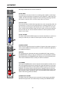
7. PAN
This control determines the position of the corresponding input signal within the stereo
image. When this control is set at its center position, the audio signal is fed with equal
levels to the left and the right master busses. Through the extensive PAN section circuit-
ry the essential sound pressure level always stays the same, no matter to what position
within the stereo image the PAN control is set.
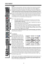
8. SIGNAL / PEAK indicator
The Signal / Peak indicator has a key function during input level adjustment of the cor-
responding channel, offering optical information of the actual signal level. It provides the
possibility to detect the risk of occurring overdrive before you would actually hear the
distortion; unlike the mixers of many other manufacturers that either only provide a PEAK
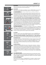
indicator or no channel indicator at all. As described before, the SIGNAL “present” LED
should blink in the rhythm of the incoming signal. If this is not the case, you have to incre-
ase the gain. If the PEAK LED, on the other hand, blinks frequently or lights up constantly,
the corresponding channel is likely to enter clipping and you have to reduce amplifi cation
using the gain control. The signal “present” LED lights at levels -30dB below clipping
while the peak LED lights at a level of -6dB below the occurrence of overdrive. It is also a
good idea to keep an eye on these indicators during a performance, to prevent the mixing
console’s input channels form clipping caused by increasing volumes.
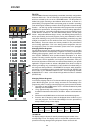
9. VOLUME
The channel fader is used to set the volume of a single channel and to establish an accu-
rately proportioned mix of all input signals. The channel faders should be positioned within
the range of -5dB to 0dB, leaving you with a degree of control that allows precise matching
of relative big differences in the channels’ level settings. The overall volume is set through
the use of the master faders. Even though the channel faders offer an additional gain of
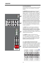
+10dB, it is good advise not to exceed the +5dB mark. Despite its special negative gain
structure, if the PowerMate’s main bus gets “overloaded” with too many “high level” input
channels, the summing amplifi er could be driven into clipping. It is more reasonable to
lower the setting of all faders by about -5dB and increase the overall output level by ele-
vating the master faders. The proportion of the mix and the overall volume stay the same
while the risk of clipping is prohibited.
27