


Model H7582 Junior Electric Guitar Kit
-11-
Electronics
Components Needed Qty
Guitar ................................................................. 1
Black Screws #3 x
3
⁄4" ....................................... 2
Black Screws #2 x
1
⁄4" ... ........ ........ ........ ........ .... 6
Silver Screws #3 x
1
⁄2" ....................................... 2
Circuit Board ......................................................
1
Pickup ................................................................ 1
Speaker ............................................................. 1
Battery Case ......................................................
1
Jack Plate ..........................................................
1
After the pickup, battery case, and speaker are
installed, solder them onto the jacks and the cir
-
cuit board.
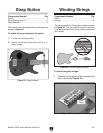
Pickup
The pickup is installed onto the front of the gui-
tar.
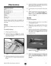
To install the pickup
:
1. Place the guitar face-side up.
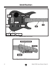
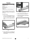
2. Insert the pickup wire (Figure 11) through
the hole in the pickup mortise and into the
circuit board mortise.
Figure 11. Pickup installation location.
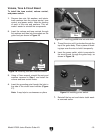
3. Insert the pickup into the mortise, positioning
both of the #3 x
3
⁄4" black screws through a
spring.
Pickup
Wire
Hole
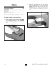
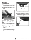
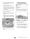
Figure 12. Speaker wires in battery case
mortise.
4. Solder the speaker wires onto the speaker as
shown on the Wiring Diagram on
Page 23
and the Electrical Components photos on
Page 24.
4. Secure the pickup to the guitar body with the
black screws. Be careful NOT to thread the
screws through the pickup wire.
5. Turn the guitar over so the back is face-side
up.
6. Solder the pickup wire onto the volume con-
trol as shown on the Wiring Diagram on
Page 23 and the Electrical Components
photos on
Page 24.
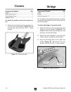
Speaker
To install the speaker:
1. Place the speaker mesh cover in the bottom
of the speaker mortise
2. Align holes on the speaker with holes in the
mortise and fasten the four #2 x
1
⁄4" black
screws.
3. Insert the two black wires on the headphone
jack through holes in the circuit board mortise
and battery case
(Figure 12) and into the
speaker mortise.