


DX8 – 13
Strip the wire back about 1/4" inch, insert the
wire as far as it will go into the appropriate hole in
the supplied Phoenix-type connector, and tighten
down the screw with a small slot-head screwdriver.
It is recommended that you use 20 or 22 gauge
wire with the Phoenix-type connectors. The
OUTPUT
connectors are wired as follows:
Pin 1 = Ground (Shield)
Pin 2 = Hot (+)
Pin 3 = Cold (–)
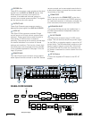
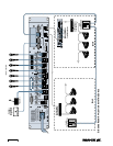
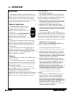
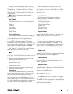
Connecting the LOGIC I/O
This is a 25-pin D-Sub connector. There are 10 logic
inputs and 10 logic outputs. They are all active-low
circuits. Use 22 gauge wire for these connections.
N/C
GROUND
N/C
LOGIC OUT 10
LOGIC OUT 9
LOGIC OUT 8
LOGIC OUT 7
LOGIC OUT 6
LOGIC OUT 5
LOGIC OUT 4
LOGIC OUT 3
LOGIC OUT 2
LOGIC OUT 1
N/C
LOGIC IN 10
LOGIC IN 9
LOGIC IN 8
LOGIC IN 7
LOGIC IN 6
LOGIC IN 5
LOGIC IN 4
LOGIC IN 3
LOGIC IN 2
LOGIC IN 1
+5VDC
LOGIC I/O
1
14
25
13
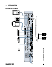
LOGIC I/O Pinout Connection
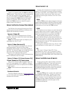
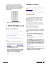
The
logic inputs
are active-low with internal pull-
up resistors connected to +5 VDC. Use a normally
open switch connected between the logic input and
ground (pin 25). When the switch is closed, the
logic input is active. Depending on the function
assigned to the logic input, a toggle switch or a
momentary switch may be used.
N/C
GROUND
N/C
LOGIC IN 10
LOGIC IN 9
LOGIC IN 8
LOGIC IN 7
LOGIC IN 6
LOGIC IN 5
LOGIC IN 4
LOGIC IN 3
LOGIC IN 2
LOGIC IN 1
LOGIC INPUT
1
14
25
13
LOGIC INPUT Connection
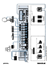
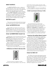
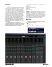
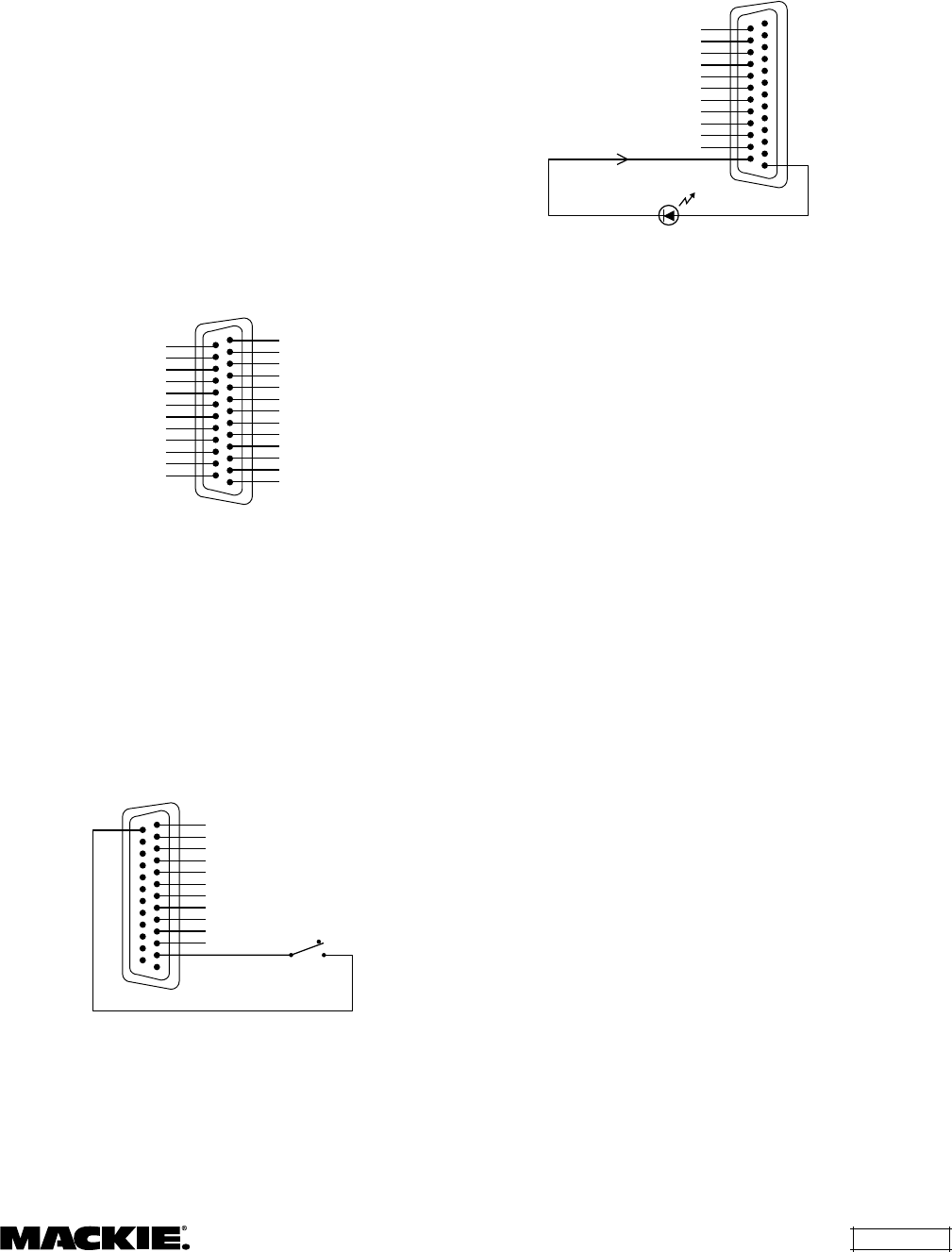
The
logic outputs
are active-low, open-collector
outputs with internal pull-up resistors. Connect the
indicator or activation circuit between the logic
output and +5 VDC (pin 1). When the output is
active, the output is 0 VDC. The logic outputs can
supply up to 10 mA of current each.
GROUND
N/C
LOGIC OUT 10
LOGIC OUT 9
LOGIC OUT 8
LOGIC OUT 7
LOGIC OUT 6
LOGIC OUT 5
LOGIC OUT 4
LOGIC OUT 3
LOGIC OUT 2
LOGIC OUT 1
10mA Maximum
+5VDC
LOGIC OUT
1
14
25
13
LOGIC OUTPUT Connection
Note: Pins 12, 13, and 24 are not used at this
time. They are reserved for future updates.
Do not
connect anything to these pins.
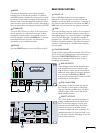
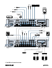
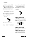
Connecting the REMOTE BUS
This is a 3-pin Phoenix-type connector
specifically for connecting the optional remote
control peripherals. Use a high-quality three-
conductor shielded cable to make this connection,
such as Belden 8451, 9451, or equivalent. The
lower the nominal capacitance of the wire, the more
distance you can have between the remote control
and the DX8 before suffering transmission losses.
Strip the wire back about 1/4" inch, insert the
wire as far as it will go into the appropriate hole in
the supplied Phoenix-type connector, and tighten
down the screw with a small slot-head screwdriver.
It is recommended that you use 18, 20, 22, or 24 gauge
wire for the remote control connections, depending
on the distance between the DX8 and the remotes.
The
REMOTE BUS
connector is wired as follows:
Pin 1 = Ground (Shield)
Pin 2 = Data + (with +24 VDC power)
Pin 3 = Data – (with +24 VDC power)
Note: See the instructions with the remote
control for more information.
AC Power Considerations
The DX8 can accept an AC voltage ranging from
90 V to 240 V without having to reconfigure the
primary wiring, due to the sophisticated design of
the switching power supply. Each DX8 draws an
average of 1 amp of AC line current at 120 VAC.
Warning: Always use a 3-conductor AC power
cord with a safety ground connection. Never
remove the ground pin or attempt to bypass it. This
is very dangerous.