


DX8 – 27
Action Definitions
Momentary
means that the logic function is
active as long as the Logic Input is held active.
When the Logic Input is inactive, the logic function
is inactive.
Latch On
means that the logic function is active
and stays active once the Logic Input changes from
inactive to active (logic high to logic low). Changing
the Logic Input from active to inactive does not
affect the logic function—it stays latched on.
Latch Off
means that the logic function turns off
(inactive) and stays off when the Logic Input
changes from a logic high to a logic low. Changing
the Logic Input from active to inactive does not
affect the logic function—it stays latched off.
Toggling
means that the logic function toggles
between the inactive and active states when the
Logic Input changes from inactive to active.
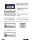
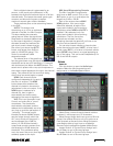
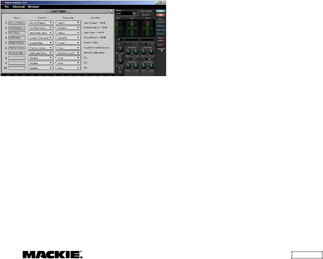
Logic Out
Click this button to open the Logic Output
window. Make the following settings and
assignments in the Logic Output window:
Applications for Logic Inputs and Outputs
Logic Inputs
Mute Groups:
This function makes it easy to
"turn off" some or all inputs instantly with a single
command (either with a Logic Input command or a
remote control) without affecting preset levels. For
example, instead of using the priority function on a
paging microphone, a Selection Remote Control
can be configured to mute all program sources
momentarily while a button is pressed to make an
announcement. Or all the choir mics in a church
application could be muted when the choir is not
singing (or, in some applications, when the choir
is
singing).
Force-on:
Use this function as a priority overide
for a microphone and to force-off lower priority
microphones. This might be useful in a board-room
application for a moderator or speaker to use, or in
a restaurant application for a paging microphone.
Force-off:
Use this to "duck" an input signal
rather than completely mute it, as with the mute
input function. For example, when the telephone
rings in a bar, the bartender can momentarily lower
the volume of the jukebox with the press of a
button while he talks on the phone.
Mute Input:
Useful where it is necessary to
temporarily mute an input signal from a remote
location. For example, in a board room a mute
button could be provided for each microphone.
Mute Output:
This function could be used to
mute a particular zone in a restaurant or office
building.
Preset Recall:
In applications where the
configuration of the system must change at various
times throughout the day or week, this function
provides an easy way to quickly change the system
configuration. For example, in a church application
there might be a preset for Sunday morning
worship service, and a different preset for Monday
evening Bible study.
Logic Outputs
Input Signal Present:
Use this logic signal to light
an LED to indicate the presence of a signal on a
microphone or line input. This could be particularly
useful when routing an input signal through
multiple DX8s, to verify the signal is present at all
intended locations.
Another example might be in a church
application where the pastor has a lavalier mic. As
he approaches the pulpit, the pulpit mic begins to
pick up his voice, triggering the Input Signal Present
to go active. This is connected to a Logic Input pin,
which forces off the lavalier mic.
Output Signal Present:
Use this logic signal to
light an LED to indicate the presence of a signal at
one of the outputs.
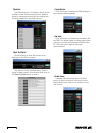
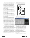
Name:
Enter a name for each Logic Output, up
to 32 characters.
Function:
Select one of 7 different functions in
this drop-down box, including Inactive, Input Signal
Present, Output Signal Present, Input Channel
Open, Output Channel Open, Preset Active, and
Priority Inactive.
Parameter:
Select the input, output, or other
parameter that is being monitored by the Logic
Output. The selections will vary depending on the
function selected for the Logic Output.
Condition:
Displays the particular condition that
must be satisfied for the Logic Output to become
active. The condition will vary depending on the
function and parameter selected for the Logic Output.
See Appendix B for a chart of the Logic Output
functional combinations available.