


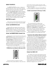
DX8 – 16
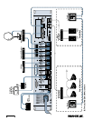
DIRECT OUTPUTS
The
DIRECT OUTPUTS
provide an unbalanced
line-level signal from each of the 8 Input channels.
This signal comes from the output of the preamplifier
stage on each input channel, prior to the A/D
converter and subsequent digital signal processing.
Use the
DIRECT OUTPUTS
to connect a continuous
music source (e.g., satellite feed, prerecorded back-
ground music, multi-disc CD player). This may connect
to a telephone system music-on-hold input, or to
provide a feed to a multi-track recorder (for recording) or
a mixing console (for additional zone coverage).
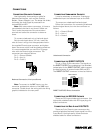
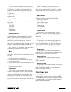
OUTPUTS A and B
These outputs provide a balanced line-level signal.
Connect these outputs to the inputs of a power amplifier.
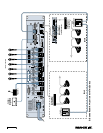
Using the RECORD Output
The
A
and
B
output signals are provided at the
RECORD
output jacks, which are industry standard
unbalanced RCA connectors. Connect these to the
Tape Input jacks on a tape deck or other recording
device to record the mix at the
BUS A
and
B
outputs.
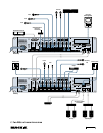
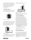
Using the REMOTE BUS Connection
Connect one or up to nine remote controls to the
REMOTE BUS
connection. Each remote control has
an 8-position DIP switch that must be set to a
unique ID. When the DX8 is first turned on, it polls
the
REMOTE BUS
and identifies the remote
controls connected to it by each unique ID.
Many of the predefined functions have two ID
addresses assigned to it to accommodate situations
where two remote controls are required to control
the same function on a single DX8.
There are two remote control versions available:
DX-SW4 Selection Remote (4-Button/4-LED)
This remote device is designed to select
functions such as preset selection, mute, and force-
on/off. Each of the four buttons controls a single
function and its associated LED displays the current
state of the function.
Refer to Appendix C for a list of the predefined
functions available for the Selection Remote Control.
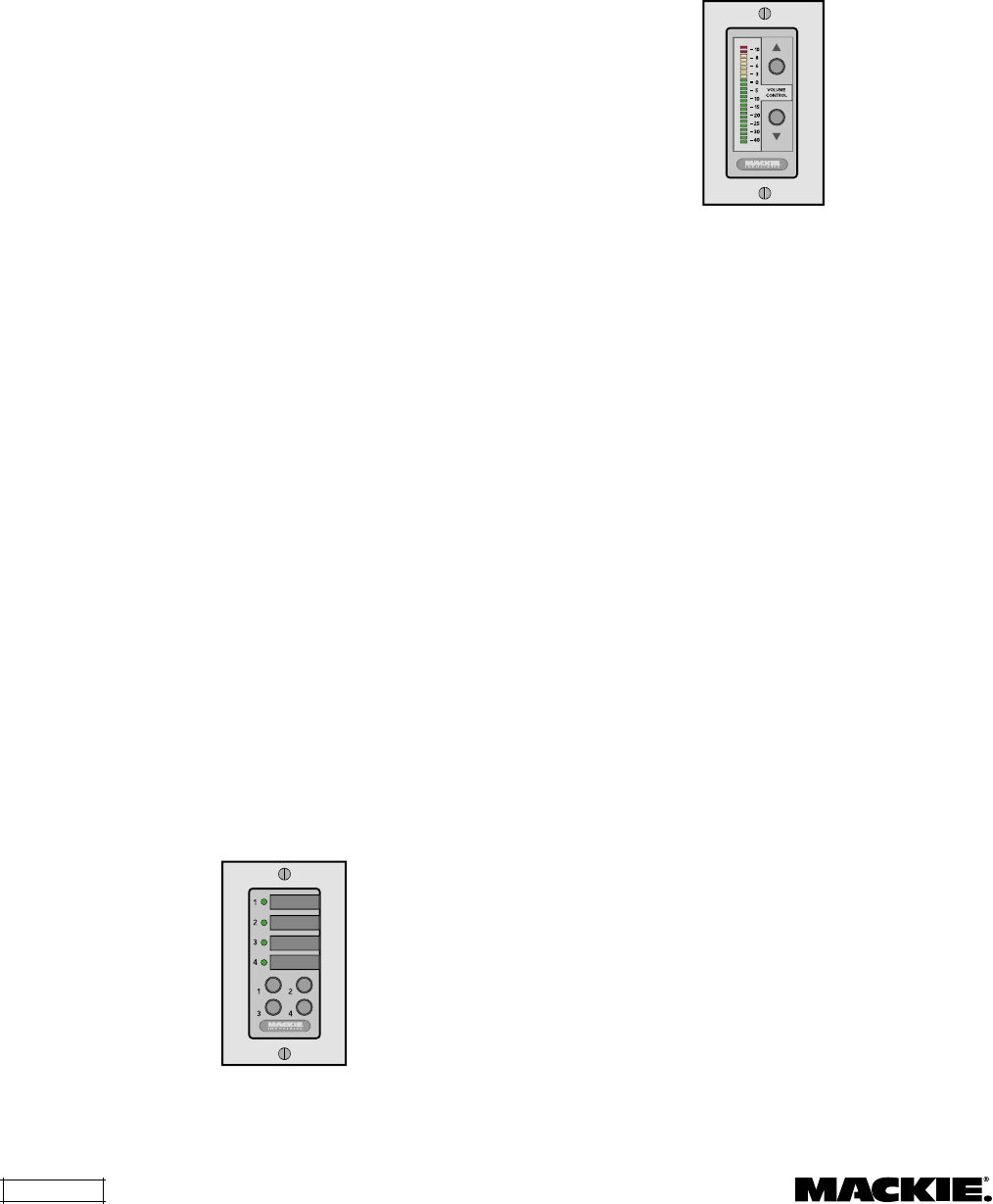
DX-RVC Level Remote (2-Button/12-LED)
This remote device can control a level,
preselected via the 8-position DIP switch, and
display the selected level on the LED meter. The
predefined functions include Input 1-8 level,
OUTPUT A
or
B MASTER
level,
OUTPUT A
and
B
Group level, and Group 1-8 level. Note that the
remote control indicates the gain setting of the
channel, and not the signal level in real time.
Refer to Appendix D for a list of the predefined
functions available for the Level Remote Control.
Connecting One or More Remote Controls
The remote control devices are connected to
the DX8 using a 3-wire half-duplex interface with
+24 VDC phantom power. The
REMOTE BUS
connection can provide power for up to nine
remotes. Provision is made to connect local power to
the remote controls if required in certain applications.
The maximum distance between the DX8 and
the remotes varies, depending on the type of cable
selected and the type of remote controls used. As a
general rule, using 22 gauge wire (at 0.014 Ω/ft. and
34 pF/ft), one remote can be up to 3000 feet away,
five remotes can be up to 2500 feet away, and eight
remotes can be up to 500 feet away before trans-
mission losses become a factor (see the instructions
with the remote control for more information).
Using the LOGIC I/O
The DX8 has 10 programmable general-purpose
logic inputs and 10 programmable general-purpose
logic outputs. The inputs are active low with internal
pull-up resistors. The outputs are active low open-
collectors with internal pull-up resistors. With the
inputs or outputs unconnected or inactive, the logic
voltage level is high (+5 V). The active state is
defined as voltage low (0 V or ground).