


Owner's Manual 11
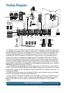
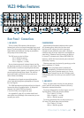
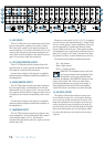
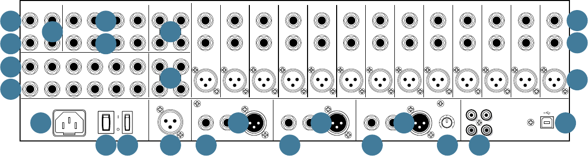
7. LEFT/RIGHT MAIN OUTPUTS: XLR & 1/4"
The male XLR connectors provide a balanced
line-level signal that represents the end of the mixer
chain, where your fully mixed stereo signal enters the
real world. Connect these to the left or right inputs of
your main power amplifiers, powered speakers, or serial
effects processor (like a graphic equalizer or
compressor/limiter). The XLR outputs are 6 dB hotter
than the TRS outputs.
The 1/4" TRS output connectors provide balanced or
unbalanced line-level signals. Connect these to the next
device in the signal chain like an external processor
(compressor/limiter), or directly to the inputs of the
main amplifier. These are the same signal that appears
at the XLR main outputs, but 6 dB lower when the XLR
is used balanced.
8. MAIN INSERTS
These 1/4" TRS jacks are for connecting serial effects
such as compressors, equalizers, deessers, or filters. The
insert point is after the mix amps, but before the main
mix fader [75]. Refer to the description of the
channel insert on the previous page to see how to make
this connection.
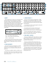
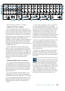
9. MONO OUT
The male XLR connector [balanced] and 1/4" TRS
output connector [balanced or unbalanced] provide
a line-level signal that is a combination of the left and
right main out [7] signals (L+R). You may use this for
a separate mix that does not require a stereo feed, or
to simply test the monaural compatibility of the stereo
mix. Again, when used balanced, the XLR signal is 6 dB
higher than that from the TRS jack.
10. MONO OUT LEVEL Control
This is a separate level control for the mono out [9].
It comes after the main mix fader [75], so turning the
main mix fader up and down does affect the mono out
signal. With this control turned all the way up, you will
have 6 dB of extra gain at the mono out.
11. GROUP OUTS 1-4
These 1/4" TRS jacks provide balanced or unbalanced
line-level signals and are typically patched to the
inputs of a multitrack deck, or to secondary amplifiers
in a complex installation.
12. GROUP INSERTS
These 1/4" TRS jacks are for connecting serial effects
such as compressors, equalizers, de-essers, or filters.
The insert point is after the mix amps, but before the
group send masters [74] (and after the built-in stereo
compressor [72]). Refer to the description of the
channel insert on the previous page to see how to make
this connection.
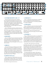
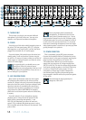
13. AUX SENDS 1-6
These 1/4" TRS connectors allow you to send balanced
or unbalanced line-level outputs to external effects
devices, headphone amplifiers, or stage monitors. These
could either be passive stage monitors powered by an
external amplifier, or powered stage monitors with built-
in power amplifiers. All six auxes are independent of
each other, so you can run up to six separate aux mixes.
Aux sends 3-4 may either be pre or post fader,
depending on the position of the pre/post switches [28].
For stage monitor work, use pre, so the stage monitors
do not increase in volume when the channel level is
adjusted. Imagine how upsetting that can be to big hairy
drummers. This allows you to set up the monitor mix
and levels just right, and not have it change every time a
channel level is adjusted.
For external processors, use post. In this way, the
feed to external processors will vary with the channel
level, so the level of any returned effect (like an echo)
will also change if the channel level is changed, keeping
them in the same ratio (wet/dry).
2404
USB
L
R
TAPE
OUTIN
MONO
MAIN OUT
INSERT LINE
TIP=SEND
RING=RETURN
(BAL/UNBAL)
RIGHT
MAIN OUT
INSERT LINE
LEFT
MAIN OUT
INSERT LINE
TIP=SEND
RING=RETURN
TIP=SEND
RING=RETURN
(BAL/UNBAL) (BAL/UNBAL)
TALKBACK
MIC
POWER
ON
PHANTOM
ON
2 1 2 16 5 4
2 16 5 4
AUX INSERTS
(TIP=SEND, RING=RETURN)
AUX SENDS
(BAL/UNBAL)
L
R
(MONO)
STEREO RETURNS
(BAL/UNBAL)
3
3
INSERT INSERT INSERT INSERT INSERT INSERT INSERT INSERT INSERT INSERT INSERT INSERT INSERT INSERT INSERT INSERT INSERT INSERT INSERT INSERT
LINE IN
(BAL/UNBAL)
LINE IN
(BAL/UNBAL)
LINE IN
(BAL/UNBAL)
LINE IN
(BAL/UNBAL)
LINE IN
(BAL/UNBAL)
LINE IN
(BAL/UNBAL)
LINE IN
(BAL/UNBAL)
LINE IN
(BAL/UNBAL)
LINE IN
(BAL/UNBAL)
LINE IN
(BAL/UNBAL)
LINE IN
(BAL/UNBAL)
LINE IN
(BAL/UNBAL)
LINE IN
(BAL/UNBAL)
LINE IN
(BAL/UNBAL)
LINE IN
(BAL/UNBAL)
LINE IN
(BAL/UNBAL)
LINE IN
(BAL/UNBAL)
LINE IN
(BAL/UNBAL)
LINE IN
(BAL/UNBAL)
LINE IN
(BAL/UNBAL)
20 19 18 17 16 15 14 13 12 11 9 8 7 6 5 4 3 2 110
MIC 20 MIC 19 MIC 18 MIC 17 MIC 16 MIC 15 MIC 14 MIC 13 MIC 12 MIC 11 MIC 10 MIC 9 MIC 8 MIC 7 MIC 6 MIC 5 MIC 4 MIC 3 MIC 2 MIC 1
X
D
R
2
M
I
C
P
R
E
X
D
R
2
M
I
C
P
R
E
X
D
R
2
M
I
C
P
R
E
X
D
R
2
M
I
C
P
R
E
X
D
R
2
M
I
C
P
R
E
X
D
R
2
M
I
C
P
R
E
X
D
R
2
M
I
C
P
R
E
X
D
R
2
M
I
C
P
R
E
X
D
R
2
M
I
C
P
R
E
X
D
R
2
M
I
C
P
R
E
X
D
R
2
M
I
C
P
R
E
X
D
R
2
M
I
C
P
R
E
X
D
R
2
M
I
C
P
R
E
X
D
R
2
M
I
C
P
R
E
X
D
R
2
M
I
C
P
R
E
X
D
R
2
M
I
C
P
R
E
X
D
R
2
M
I
C
P
R
E
X
D
R
2
M
I
C
P
R
E
X
D
R
2
M
I
C
P
R
E
X
D
R
2
M
I
C
P
R
E
3 2 14
GROUP OUTS
(BAL/UNBAL)
GROUP INSERTS
(TIP=SEND, RING=RETURN)
3 2 14
MONITOR
(MONO)
PHONES
MONITOR
L
R
L
R
23/24 21/22
(MONO)
(BAL/UNBAL) (BAL/UNBAL)
REVISION
SERIAL NUMBER
WARNING:
TO REDUCE THE RISK OF FIRE OR ELECTRIC
SHOCK, DO NOT EXPOSE THIS EQUIPMENT TO RAIN OR
MOISTURE. DO NOT REMOVE COVER. NO USER SERVICEABLE
PARTS INSIDE. REFER SERVICING TO QUALIFIED PERSONNEL.
AVIS: RISQUE DE CHOC ELECTRIQUE — NE PAS OUVRIR
LEVEL
OUTPUT
OO
+6
3
14
20
2
13
1
16 11
17 12
22 7 7 9 18
21 19
415
5
10888 6