


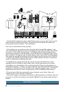
12 VLZ3 4•Bus
2404
USB
L
R
TAPE
OUTIN
MONO
MAIN OUT
INSERT LINE
TIP=SEND
RING=RETURN
(BAL/UNBAL)
RIGHT
MAIN OUT
INSERT LINE
LEFT
MAIN OUT
INSERT LINE
TIP=SEND
RING=RETURN
TIP=SEND
RING=RETURN
(BAL/UNBAL) (BAL/UNBAL)
TALKBACK
MIC
POWER
ON
PHANTOM
ON
2 1 2 16 5 4
2 16 5 4
AUX INSERTS
(TIP=SEND, RING=RETURN)
AUX SENDS
(BAL/UNBAL)
L
R
(MONO)
STEREO RETURNS
(BAL/UNBAL)
3
3
INSERT INSERT INSERT INSERT INSERT INSERT INSERT INSERT INSERT INSERT INSERT INSERT INSERT INSERT INSERT INSERT INSERT INSERT INSERT INSERT
LINE IN
(BAL/UNBAL)
LINE IN
(BAL/UNBAL)
LINE IN
(BAL/UNBAL)
LINE IN
(BAL/UNBAL)
LINE IN
(BAL/UNBAL)
LINE IN
(BAL/UNBAL)
LINE IN
(BAL/UNBAL)
LINE IN
(BAL/UNBAL)
LINE IN
(BAL/UNBAL)
LINE IN
(BAL/UNBAL)
LINE IN
(BAL/UNBAL)
LINE IN
(BAL/UNBAL)
LINE IN
(BAL/UNBAL)
LINE IN
(BAL/UNBAL)
LINE IN
(BAL/UNBAL)
LINE IN
(BAL/UNBAL)
LINE IN
(BAL/UNBAL)
LINE IN
(BAL/UNBAL)
LINE IN
(BAL/UNBAL)
LINE IN
(BAL/UNBAL)
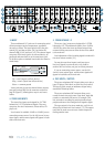
20 19 18 17 16 15 14 13 12 11 9 8 7 6 5 4 3 2 110
MIC 20 MIC 19 MIC 18 MIC 17 MIC 16 MIC 15 MIC 14 MIC 13 MIC 12 MIC 11 MIC 10 MIC 9 MIC 8 MIC 7 MIC 6 MIC 5 MIC 4 MIC 3 MIC 2 MIC 1
X
D
R
2
M
I
C
P
R
E
X
D
R
2
M
I
C
P
R
E
X
D
R
2
M
I
C
P
R
E
X
D
R
2
M
I
C
P
R
E
X
D
R
2
M
I
C
P
R
E
X
D
R
2
M
I
C
P
R
E
X
D
R
2
M
I
C
P
R
E
X
D
R
2
M
I
C
P
R
E
X
D
R
2
M
I
C
P
R
E
X
D
R
2
M
I
C
P
R
E
X
D
R
2
M
I
C
P
R
E
X
D
R
2
M
I
C
P
R
E
X
D
R
2
M
I
C
P
R
E
X
D
R
2
M
I
C
P
R
E
X
D
R
2
M
I
C
P
R
E
X
D
R
2
M
I
C
P
R
E
X
D
R
2
M
I
C
P
R
E
X
D
R
2
M
I
C
P
R
E
X
D
R
2
M
I
C
P
R
E
X
D
R
2
M
I
C
P
R
E
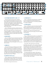
3 2 14
GROUP OUTS
(BAL/UNBAL)
GROUP INSERTS
(TIP=SEND, RING=RETURN)
3 2 14
MONITOR
(MONO)
PHONES
MONITOR
L
R
L
R
23/24 21/22
(MONO)
(BAL/UNBAL) (BAL/UNBAL)
REVISION
SERIAL NUMBER
WARNING:
TO REDUCE THE RISK OF FIRE OR ELECTRIC
SHOCK, DO NOT EXPOSE THIS EQUIPMENT TO RAIN OR
MOISTURE. DO NOT REMOVE COVER. NO USER SERVICEABLE
PARTS INSIDE. REFER SERVICING TO QUALIFIED PERSONNEL.
AVIS: RISQUE DE CHOC ELECTRIQUE — NE PAS OUVRIR
LEVEL
OUTPUT
OO
+6
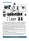
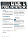
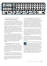
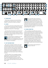
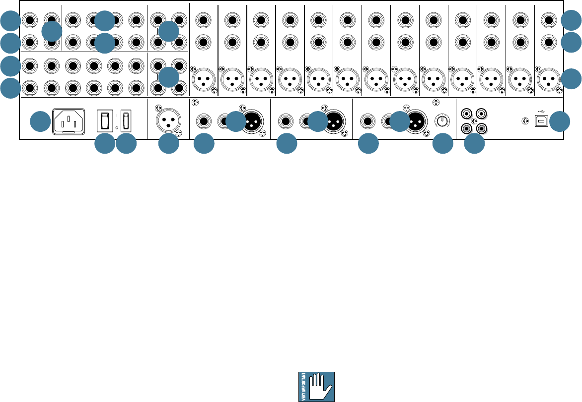
14. AUX INSERTS
These 1/4" TRS jacks are for connecting serial effects
such as compressors, equalizers, de-essers, or filters.
The insert point is after the mix amps, but before the
aux send masters [52] and the solo switch [60] (so you
may hear the external processor when soloing the aux
send). Refer to the description of the channel insert on
page 11 to see how to make this connection.
15. LEFT/RIGHT MONITOR OUTPUTS
These 1/4" TRS jacks provide a balanced line-level
signal that may be used to provide an additional main
mix output or to monitor soloed channels.
Connect these outputs to the inputs of an amplifier,
powered speaker, headphone distribution amplifier, or
recording device.
16. MONO MONITOR OUTPUT
This 1/4" TRS output connector provides a balanced
line-level signal that is a combination of the left and
right monitor out [15] signals (L+R). You may use this
for a separate mix that does not require a stereo feed, or
to simply test the monaural compatibility of the stereo
mix.
Connect these outputs to the inputs of an amplifier,
powered speaker, headphone distribution amplifier, or
recording device.
17. HEADPHONE OUTPUT
This 1/4" TRS connector supplies the output to your
stereo headphones. It is the same signal that is routed
to the monitor outputs [15-16]. The volume is
controlled with the phones knob [69], right next to the
monitor knob [68].
Whenever a solo switch [41, 49, 53, 55, 73] is engaged,
you will only hear the soloed channel(s), 2-track return,
aux(es), and/or group(s) in the headphones. This gives
you the opportunity to audition the channels before
they are added to the main mix. (Solo signals reaching
the headphones are not affected by the channel level or
main level (except in AFL mode), therefore turn down
the phones level first, as soloed channels may be loud.)
The phones output follows standard conventions:
Tip = Left channel
Ring = Right channel
Sleeve = Common ground
WARNING: The headphone amp is loud, and
can cause permanent hearing damage. Even
intermediate levels may be painfully loud
withsomeheadphones.BECAREFUL!Alwaysturnthe
phones level control [69] all the way down before
connecting headphones or pressing a solo switch, or
doing anything new that may affect the headphone
volume. Then turn it up slowly as you listen carefully.
18. USB INPUT/OUTPUT
The built-in USB interface allows for some power-
ful and flexible routing. It is a 4x2 interface allowing
you to record up to four streams from the mixer, or to
input stereo playback from a computer and route it to
nearly any output or pair of outputs on the mixer. To
use this feature with a PC, first download the PC ASIO
driver from www.mackie.com. If connecting to a Mac,
the mixer will show up as a 4x2 device with no driver
required.
3
14
20
2
13
1
16 11
17 12
22 7 7 9 18
21 19
415
5
10888 6