


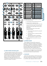
20 VLZ3 4•Bus
The OL (overload) LED will come on when the
channel’s input signal is too high. This should be
avoided, as distortion will occur. If the OL LED comes
on regularly, check that the gain control [23] is set
correctly for your input device, and that the channel
EQ is not set with too much boost. The OL LED will
also illuminate when a channel's mute switch [38] is
engaged.
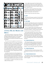
40. SIG LED
This LED also indicates the channel’s signal level
after the gain and EQ controls, but just before the
channel’s level. So even if the level is turned down, you
can see if a signal is present.
The SIG (signal) LED will come on when the
channel’s input signal (at least -20 dBu) is present.
It should illuminate non-stop if signal above 0 dBu is
present in that channel. This LED will be solid when a
channel's solo switch [41] is engaged.
41. SOLO
Whenever a channel's solo switch is engaged, you
will hear only the soloed channel(s) in the headphones
and monitor outputs. This gives you the opportunity to
audition the channels before they are added to the main
mix. In PFL mode you can hear the solo signal, even
when the channel's fader is down.
Solo is also used to set the gain of each channel
correctly. When a channel is soloed, you can adjust the
channel gain [23] until your input source reaches the
level of the 0 dB LED of the left meter. Select PFL on
the SOLO MODE switch [60] for gain setting.
Solo signals reaching the headphones and
monitor outputs are not affected by the
channel level (unless the SOLO MODE switch
is set to AFL) or main level; therefore, turn
down the phones level [69] and monitor level [68] first,
as soloed channels may be loud.
The rude solo light [59] will turn on as a reminder
that what you are listening to in the headphones and
control room is just the soloed channel(s), 2-track
return, stereo return(s), aux(es), and/or group(s). If
the solo source is an input channel, that channel's SIG
(signal) LED [40] will illuminate when that channel is
soloed.
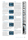
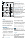
42. ASSIGN
Alongside each channel fader are three buttons
referred to as channel assignment switches. Used in
conjunction with the channel's pan knob [37], they
are used to determine the destination of the channel's
signal.
With the pan knob at the center detent, the left and
right sides receive equal signal levels (main mix L-R,
group 1-2, and group 3-4). To feed only one side or the
other, turn the pan knob accordingly.
If you are doing a mixdown to a 2-track, for example,
simply engage the main mix switch on each channel
that you want to hear, and they will be sent to the main
mix bus. If you want to create a group of certain
channels, engage either the 1-2 or 3-4 switches instead
of the main mix, and they will be sent to the appropriate
group faders. From there, the groups may be sent back
to the main mix (using the group assign switches [73]
above the group faders [74]), allowing you to use the
group faders as a master control for those channels.
If you are creating new tracks or bouncing existing
ones, you will also use the 1-2 and 3-4 switches, but not
the main mix switch. Here you do not want the groups
sent back into the main mix bus, but sent out, via the
group out jacks [11], to your multitrack inputs.
43. CHANNEL FADER
This is the last control in a channel’s signal path, and
it adjusts the level of each channel onto the main mix.
The “U” mark indicates unity gain, meaning no increase
or decrease of signal level. All the way up provides an
additional 10 dB, should you need to boost a section of
a song. If you find that the overall level is too quiet or
too loud with the level near unity, check that the gain
control [23] is set correctly.
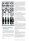
44. FX1 and FX2
When engaged, these switches, located just below the
stereo channels' gain controls [23], indicate that you
want to return the internal FX processor signal to the
stereo channel. The TRS inputs are disengaged when
the switch is depressed.
Remember to turn the FX processor level
controls to aux 1/2 and main all the way down
to avoid double-bussing the FX return.
See Appendix E (page 37) for a list of the effects
provided and a description of each one.
45. USB Switch
The USB switch on the last stereo channel provides
stereo playback of iTunes
®
, or a DAW via the USB
connection. Like any other input, this signal may also
be EQ'd, sent to an aux bus, or mixed in with the other
signals and assigned to subgroups or main outs. This
switch overrides both the TRS inputs [5] and the FX2
switch [44].