


22 VLZ3 4•Bus
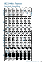
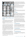
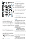
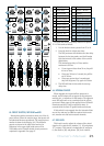
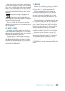
51. USB OUT
These two switches allow for monstrous flexibility on
the four recordable signals. The default switch
configuration (disengaged) routes subgroups 1-4 over
the USB connection to your favorite DAW software for
a "mix it later" 4-track recording. Engaging the switch
on the left allows the main L-R mix to be recorded for
convenient stereo mixes of the show. The other switch
allows aux 5/6 to be sent to the DAW for a unique stereo
recording or the use of DAW plug-ins as effects.
52. MASTER AUX SENDS 1-6
These knobs provide overall control over the aux send
levels, just before they are delivered to the aux send
outputs [13]. These knobs go from off to +15 db when
turned all the way up.
This is usually the knob you turn up when the lead
singer glares at you, points at his stage monitor, and
sticks his thumb up in the air. (It would follow that if
the singer stuck his thumb down, you’d turn the knob
down, but that never happens.)
Keep in mind that aux sends 3-4 may either be
pre or post fader, depending on the position of
the channel's aux pre/post switch [28].
53. MASTER AUX SENDS SOLO
This button allows you to solo an individual aux send.
If you are using the aux sends to feed your stage
monitors, you may use these buttons to check your
monitor mix. The rude solo LED [59] will flash to let
you know the solo system is active.
The aux send solo is AFL and is not affected by the
solo mode switch (PFL/AFL) [60], except that in PFL
mode only the left meter indicates the signal.
54. STEREO RETURNS 1-2 to AUX 1-4/MAIN
These ten controls set the overall level of line signals
received from the stereo return 1-2 inputs [5]. These
controls range from off to +15 db of gain when fully
clockwise, to compensate for low-level effects.
Signals passing through these controls go directly to
the main mix and aux 1-4 buses where they are
combined with signals from the channels.
55. STEREO RETURNS SOLO
This button allows you to solo a stereo return. The
rude solo LED [59] will flash to let you know that the
solo system is active. Since this is an input, this signal is
affected by the PFL/AFL master switch.
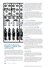
56. 48V LED
Most modern professional condenser mics require
48V phantom power, which lets the mixer send
low-current DC voltage to the mic’s electronics
through the same wires that carry audio. (Semi-pro
condenser mics often have batteries to accomplish the
same thing.) “Phantom” owes its name to an ability to
be “unseen” by dynamic mics (Shure SM57/SM58, for
instance), which don’t need external power and aren’t
affected by it anyway.
Phantom power for all mic inputs (except the talk-
back mic) may be selected by pressing up on the
mixer's phantom [21] switch.
Never plug single-ended (unbalanced)
micro phones, or ribbon mics into the mic
input jacks if phantom power is on. Do not
plug instrument outputs into the mic XLR input jacks
with phantom power on, unless you are certain it is safe
to do so.
57. POWER LED
This green LED will illuminate when the mixer is
turned on, as a reminder of how on it really is. If it is
not on, then it is off, and the mixer becomes a rather
nice weight for keeping your morning newspaper from
blowing away in the wind.
If it does not turn on, make sure the power cord is
correctly inserted at both ends, the local AC mains
supply is active, and the power switch [20] is on.
2404
SOLO
1
SOLO
1
2
3
4
2
SOLO
SOLO MODE
MAIN
STEREO RETURNSAUX MASTERS
SOLO
SOLO
SOLO
SOLO
+15
OO
+15
OO
+15
OO
SOLO
AUX
AUX
AUX
AUX
MAIN
MIX
0 dB=0 dBu
RUDE SOLO
20
10
7
4
2
0
2
4
7
10
20
30
LEFT RIGHT
SOLO
+20
OO
TO MAIN
PFL
AFL
GRP 1-2
CH 1-2 CH 3-4
AUX 5-6
PWR
48V
TAPE
USB
2-TRACK RETURN USB OUT
GRP 3-4
MAIN L/R
LEVEL
SET
U
+15
OO
U
+15
OO
U
+15
OO
U
+15
OO
U
+15
OO
U
+15
OO
U
+15
OO
U
+15
OO
U U
U
+15
OO
3
1
5
6
2
U
U
+15
OO
U
+15
OO
+15
OO
U
+15
OO
U
4
U
12V
0.5A
50%
25% 75%
0% 100%
SUCK
46 47
48
52
54
55 60
59
58
56 57
49
53
50 51