


2 3
KM 100
Die Mikrophone werden mit 48 V, 2 mA phantom-
gespeist (IEC 1938). Feldbetriebsübertragungsfak-
tor je nach Mikrophonkapsel 10...15 mV/Pa ent-
sprechend –40...–36 dB re. 1 V/Pa. In den Aus-
gangsstufen befindet sich jeweils ein 10 dB-
Schalter zum Absenken des Übertragungsmaßes, in
der Ausgangsstufe KM 100 F zusätzlich ein Schal-
ter zur Bassabsenkung. Der Dynamikumfang reicht
von ca. 16 dB-A (Ersatzgeräuschpegel) bis ca.
138 dB SPL (Grenzschalldruckpegel). Das sind
122 dB.
2. Das Kleinmikrophon-System
KM 100
2.1 Allgemeines, Beschreibung
KM 100 ist das variable Kondensator-Kleinmikro-
phon-System aus der Typenreihe „fet 100
®
“. Das
System ist variabel, weil es eine Reihe unter-
schiedlicher Kondensatorkapseln mit verschiede-
nen Richtcharakteristiken anbietet und weil es
eine Vielzahl an Zubehör gibt, das zwischen die
Kapseln und die Ausgangsstufen geschraubt wer-
den kann. Dadurch lassen sich die Mikrophone an
unterschiedlichste Aufgaben besonders leicht und
gut anpassen. Ein eventuell im Fernsehbild, auf
der Bühne oder im Konzertsaal sichtbares Mikro-
phon kann besonders unauffällig gehalten wer-
den.
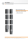
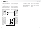
KM 100 heißt Kleinmikrophon-System, weil die
Mikrophone nur 92 mm lang sind und einen Durch-
messer von 22 mm haben. Das Mikrophon besteht
aus der Kondensatorkapsel und der Ausgangsstu-
fe KM 100. Beide Teile können auseinanderge-
schraubt werden. Das Kapselteil kann auf Zubehör
wie
• Kabel,
• Kapselverlängerungen,
• Stativgelenke,
• Tischständer,
• Schwanenhälse,
• Stereohalterungen und
• Abhängevorrichtungen
geschraubt werden und ist dabei als Kapselteil nur
ca. 35 mm lang (AK 20: ca. 50 mm).
Die Ausgangsstufe kann über ein nur ca. 3 mm dik-
kes Kabel bis etwa 50 m vom Kapselteil abgesetzt
werden.
Inhaltsverzeichnis
1. Kurzbeschreibung
2. Das Kleinmikrophon-System KM 100
2.1 Allgemeines, Beschreibung
2.2 Die verschiedenen aktiven Kapseln
2.3 Ausgangsstufe KM100
2.4 Ausgangsstufe KM 100 F
3. Stromversorgung
3.1 Phantomspeisung
3.2 Betrieb mit Netzgeräten
3.3 Batteriespeisung
3.4 Betrieb an unsymmetrischen oder mitten-
geerdeten Eingängen
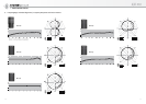
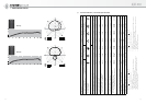
4. Frequenzgänge und Polardiagramme
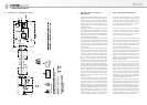
5. Technische Daten
6. Schaltbild KM 100
7. Einige Hinweise zur Pflege von Mikrophonen
8. Zubehör
1. Kurzbeschreibung
KM 100 ist das variable Kondensator-Kleinmikro-
phon-System aus der Typenreihe „fet 100
®
“. Es
besteht aus: aktiven Kapseln mit den Richtcha-
rakteristiken Kugel, breite Niere, Niere, Niere mit
abgesenktem Bassbereich, Hyperniere und Acht,
zwei unterschiedlichen Ausgangsstufen und um-
fangreichem Zubehör für unterschiedlichste Kap-
selmontage.
Das transformatorlose Schaltungskonzept zeichnet
sich aus durch besonders niedriges Eigengeräusch
und höchste Aussteuerbarkeit, besonders saubere,
freie und verfärbungsfreie Klangübertragung. Die
Ausgangsstufen haben einen symmetrischen,
transformatorlosen Ausgang.
Der 3-polige XLR-Stecker hat jeweils folgende
Belegung:
Pin 1: 0 V/Masse
Pin 2: Modulation (+Phase)
Pin 3: Modulation (–Phase)
Table of Contents
1. Summarized Description
2. The KM 100 Miniature Microphone System
2.1 General Information, Description
2.2 The Various Active Capsules
2.3 KM 100 Output Stage
2.4 KM 100 F Output Stage
3. Power Supply
3.1 Phantom Powering
3.2 ac Supply Operation
3.3 Battery Powering
3.4 Operation with Unbalanced or Center Tap
Grounded Inputs
4. Frequency Responses and Polar Patterns
5. Technical Specifications
6. Circuit Diagram KM 100
7. Some Remarks on Microphone Maintenance
8. Accessories
1. A Short Description
The KM 100 is the variable condenser miniature
microphone system of the “fet 100
®
” Series. It
consists of: active capsules with the directional
characteristics omnidirectional, wide-angle car-
dioid, cardioid, cardioid with bass roll-off, hyper-
cardioid and figure-8, two different output stages
and a comprehensive range of accessories for
widely varying methods of capsule mounting.
The main points of excellence of the transformer-
less circuit design are: remarkably low intrinsic
noise and high output capability and particularly
clean, free and colorless sound reproduction. The
output stages have a balanced, transformerless
output.
The 3-pin XLR plug connector is wired as follows:
Pin 1: 0 V/ground
Pin 2: Modulation (+phase)
Pin 3: Modulation (–phase)
The microphones are phantom powered at 48 V, 2 mA
(IEC 1938). Field sensitivity, depending on capsule
10...15 mV/Pa, corresponding to –40...–36 dB re.
1 V/Pa. Both output stages incorporate a 10 dB
preattenuation switch, the KM 100 F output stage
has an additional low frequency roll-off switch.
The dynamic range extends from approximately
16 dB-A (equivalent noise level) to approximate-
ly 138 dB SPL i.e. 122 dB.
2. The KM 100 Miniature
Microphone System
2.1 General Information, Description
The KM 100 is the variable condenser miniature
microphone system of the “fet 100
®
” Series. The
system is variable because it offers a number of
different condenser capsules with various direc-
tional characteristics and because a wide range of
accessories can be supplied, which are simply
screwed between the capsules and the output
stages. The microphones can thus be easily and
effectively used for an infinitely wide variety of
purposes. A visible microphone in a television
scene, on the stage or in the concert hall can thus
be kept extremely small and unobtrusive.
The KM 100 is called a miniature microphone sys-
tem because the microphones are a mere 92 mm
long and 22 mm in diameter. The microphone con-
sists of the condenser capsule and the KM 100 out-
put stage. Both these parts can be unscrewed from
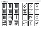
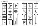
each other. The capsule section can be screwed to
accessories, such as
• cables,
• capsule extensions,
• stand mounts,
• table stands,
• goosenecks,
• stereo mounts and
• auditorium hangers
and is not more than about 35 mm long (AK 20 ap-
proximately 50 mm).
The output stage can be operated at a distance of
up to 50 m from the capsule section via a cable
only about 3 mm thick.