


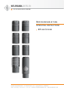

16 17
KM 100
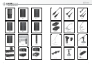
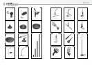
8. Zubehör
Zubehör-Liste
8.1 Kabel
8.2 Matrixverstärker MTX 191 A
8.3 Kapselverlängerungen KVF...
8.4 Stativgelenke SG..., DS... und SGE 100
8.5 Tischflansch, Tisch- und Fußbodenständer
MF..., MF-AK und TF 221 c
8.6 Stativverlängerungen STV...
8.7 Schwanenhälse SMK...
8.8 Stereohalterungen für zwei abgesetzte
Kapseln STH...
8.9 Mikrophonneigevorrichtungen MNV...
8.10 Standrohr SR 100 und Kabeladapter KA 100
8.11 Elastische Aufhängungen EA... und DA...
8.12 Windschirme WNS... und WS 100
8.13 Windschutzkörbe WKD... für Doppelaufhän-
gungen
8.14 Windjammer WJ-AK und WJ-KM
8.15 Popschutz PS 15
8.16 Schallbeugungskugel SBK 130
Zubehör-Beschreibung
8.1 Kabel
8.1.1 Kabel IC 3 mt zum Anschluss des kompletten
Mikrophons bzw. der Ausgangsstufe
Die akustischen Eigenschaften der Mikrophone
werden auch durch sehr lange (Neumann-) Kabel
nicht beeinflusst. Erst bei Kabellängen deutlich
über 300 m macht sich ein Abfall im oberen Fre-
quenzbereich bemerkbar.
Andere Kabellängen und Kabelmaterial ohne
Steckverbinder sind auf Wunsch lieferbar.
Weitere Artikel sind im Katalog „Zubehör“ be-
schrieben.
IC 3 mt ................sw ......... Best.-Nr. 06543
Mikrophonkabel mit Doppeldrallumspinnung als
Abschirmung. Ø 5 mm, Länge 10 m. XLR 3 Steck-
verbinder, schwarzmatt.
8. Accessories
Accessories Listing
8.1 Cables
8.2 MTX 191 A Matrix Amplifier
8.3 KVF... Capsule Extensions
8.4 SG..., DS... and SGE 100 Stand Mounts
8.5 Table Flange, Table and Floor Stands
MF..., MF-AK und TF 221 c
8.6 STV... Stand Extensions
8.7 SMK.... Goosenecks
8.8 STH... Stereo Mounts for two Remote Capsule
Sections
8.9 MNV... Auditorium Hangers
8.10 SR 100 Stand Tube and KA 100 Cable Adapter
8.11 EA... and DA... Elastic Suspensions
8.12 WNS... and WS 100 Windscreens
8.13 WKD... Windscreens for Double Mounts
8.14 WJ-AK, WJ-KM Windjammers
8.15 PS 15 Popscreen
8.16 SBK 130 Sound Diffraction Sphere
Accessories Description
8.1 Cables
8.1.1 IC3mt Cable for Connecting the Complete
Microphone or the Output Stage
The electroacoustic properties of the micro-
phones are not affected even by very long (Neu-
mann) cables. However, if cables are well over
300 m, a fall-off in the upper frequency range
becomes apparent.
Special cable lengths and cable material with-
out connectors can be made to order.
Further articles are described in the “Accesso-
ries” catalog.
IC 3 mt.................blk........... Cat. No. 06543
Microphone cable with double twist (double he-
lix) braiding as shield. Ø 5 mm, length 10 m.
XLR 3 connectors, matte black.
8.1.2 Kabel LC 3 KA zum Anschluss des
abgesetzten Kapselteils an die Ausgangsstufe
Die aktive Kapsel kann von der Ausgangsstufe
abgesetzt betrieben werden. Dazu wird das Ver-
bindungskabel LC 3 KA benötigt.
LC 3 KA (5 m) .....sw ......... Best.-Nr. 08408
LC 3 KA (10 m) ...sw ......... Best.-Nr. 08409
Das LC 3 KA verbindet aktive Kapseln AK... mit
der Ausgangsstufe KM 100. Ø 3,5 mm, Länge
5 oder 10 m.
8.1.3 Adapterkabel AC 30 zum Anschluss der
Stereokombination an MTX 191 (A)
AC 30 (5 m) ....................... Best.-Nr. 08418
Y-Kabel, 5 m lang, zum Anschluss aktiver Kap-
seln, z.B. AK 20 und AK 40 als MS-Stereokombi-
nation an den Matrixverstärker MTX 191 (A).
Wahlweise XY- oder MS-Signale liegen dann am
Ausgang des MTX 191 (A) vor. Der Aufnahme-
winkel wird elektrisch fernumgeschaltet. Die
Ausgangsstufen KM 100 werden nicht benötigt.
Kennzeichnung: gelb für Kanal 1 (Niere), rot für
Kanal 2 (Acht).
8.2 Matrixverstärker MTX191 A
MTX 191 A ..........sw ......... Best.-Nr. 07331
Der Matrixverstärker MTX 191 A dient zur Matri-
zierung der MS-Mikrophonsignale des Richtrohr-
Stereomikrophons RSM 191 bzw. der aktiven
Kapseln AK 20 und AK 40. Der Pegel des Seiten-
signals kann unabhängig von der Wahl der Aus-
gangssignale (MS oder XY) verändert werden.
Dies geschieht mit einem Drehschalter in 3-dB-
Schritten von –9 dB bis +6 dB relativ zum Pegel
des Mittensignals. Der Aufnahmewinkel ist in
Stufen zwischen 60° und 170° einstellbar.
Am Ausgang liegt wahlweise das MS- oder das
XY-Signal, welches durch Summen- (X = M + S)
bzw. Differenzbildung (Y = M – S) aus dem MS-Si-
gnal gewonnen wird. Die Umschaltung erfolgt mit
einem Drehschalter auf der Frontseite. In beiden
Positionen kann eine Links-Rechts-Vertauschung
geschaltet werden, falls das Mikrophon während
der Aufnahme um seine Achse gedreht wird.
Gegen tieffrequente Störgeräusche ist ein
schaltbares Hochpassfilter 40(LIN)/80/200 Hz
eingebaut. Matrixverstärker Mikrophon werden
8.1.2 LC3 KA Cable for Connecting the
Remote Capsule Section to the Output Stage
The active microphone capsule can be operated
remotely from the output stage, for which the
LC 3 KA connecting cable is required.
LC 3 KA (5 m) ..... blk........... Cat. No. 08408
LC 3 KA (10 m) ... blk........... Cat. No. 08409
The LC 3 KA connects active capsules AK... with
the KM 100 output stage. Ø 3.5 mm, length 5 or
10 m.
8.1.3 AC30 Adapter Cable to connect a Stereo
Combination with MTX 191 (A)
AC 30 (5 m) ......................... Cat. No. 08418
Y-cable, 5 m long, to connect two active cap-
sules, e.g. AK 20 and AK 40 as MS stereo couple
directly to the MTX 191(A) matrix amplifier. XY or
MS signals are then available at the XLR 5 out-
put connector of the MTX 191 (A). The recording
angle is electrically remote controlled. KM 100
output stages are not required. Markings: yellow
for channel 1 (cardioid), red for channel 2 (fig-
ure-8).
8.2 MTX 191 A Matrix Amplifier
MTX 191 A.......... blk........... Cat. No. 07331
The MTX 191 A matrix amplifier is used for pro-
cessing the MS microphone signals of the
RSM 191 shotgun stereo microphone, or the ac-
tive capsules AK 20 and AK 40. The level of the
side signal is variable, independent of which
output mode is selected (MS or XY). It is adjust-
ed through a rotary switch in 3 dB steps from
–9 dB to +6 dB, relative to the level of the mid-
dle signal. Consequently the pickup angle is var-
ied in steps between 60° and 170°.
Depending on the position of the rotary switch
on the front of the matrix amplifier the output
provides either an MS- or XY-signal. The XY-sig-
nal is obtained from the MS-signal by summa-
tion (X = M + S) or subtraction (Y = M – S). In both
modes an electric left-right-inversion is alterna-
tively possible if during the recording the micro-
phone is turned upside-down.
To suppress low frequent interfering noise the
matrix amplifier has a switchable high-pass fil-
ter at 40(LIN)/80/200 Hz. The power for both