


8
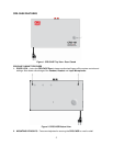
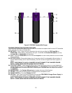
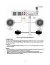
Figure 6. CRS-CASE Bottom Side Panel
CRS-CASE BOTTOM SIDE PANEL FEATURES
17. AC POWER CORD – One, three prong AC cord connects to a standard 110VAC/60Hz outlet.
Provides AC power to the CRS-101.
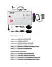
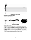
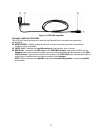
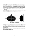
Figure 7. CRS-IRS IR Sensor
CRS-IRS IR SENSOR FEATURES
18. MINI PLUG – One, 3.5mm mini plug connects to one of the three IR Sensor Jacks on the CRS-
CASE Side Panel.
19. CABLE – 50’ cable allows the IR Sensors to be positioned away from the CRS-CASE for optimum
coverage for reception of IR pulses from the CRS IR Microphones.
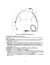
20. ON LED – One, LED illuminates green to indicate that the CRS System is ON and the IR Sensors
are connected and active.
21. IR SENSOR – Senses the IR pulses output from the CRS IR Microphones. Must be positioned to
have clear ‘line-of-sight’ to the classroom and any location that the CRS Microphones may be used.
The IR Sensor senses IR in an omni-directional pattern (140° off-axis) and will also sense IR
reflected off the ceiling, wall and hard floor surfaces. It has a range of 66 feet.