


15
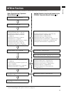
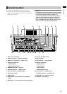
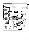
Overview
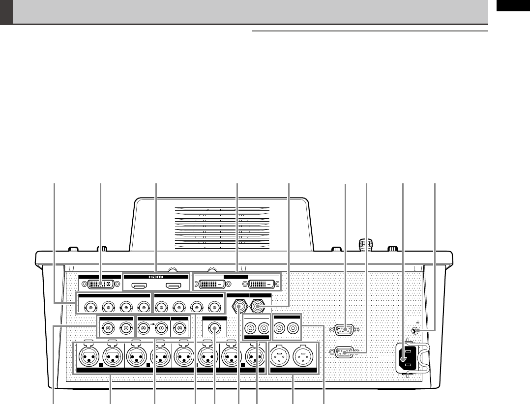
Connector Area (Rear)
1 SDI IN 1 to 4 connectors
2 DVI-I IN connector ( pages 32, Vol.2-28)
3 HDMI IN 1, 2 connectors ( pages 17, 18)
4 DVI-D OUT connectors
• PGM connector
• MULTI VIEW connector
5 PHONES connector ( page 33)
6 RS-232C connector ( page Vol.2-28)
7 TALLY connector ( page Vol.2-29)
8 AC IN power socket
9 GND terminal
10 AUDIO OUT 2 L and R connectors (unbalanced
output)
11 AUDIO OUT 1 L and R connectors (balanced output)
12 AUX IN L and R connectors
13 MIC connector
14 GPI connector ( page Vol.2-26)
15 SDI OUT connectors
• PGM connector
• PVW connector
• AUX connector
• MULTI VIEW connector
16 G/L connector ( page Vol.2-28)
ADV-REF connector ( page Vol.2-28)
17 AUDIO IN 1 to 4 L and R connectors
18 VIDEO IN 1, 2 connectors
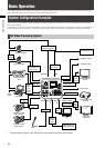
For devices and signals which can be connected to
each connector, see “System Conguration Examples”
(
page 16) and “Example Connections with 3D Camera”
( pages Vol.2-22 to 24).
NOTE
For the DVI-I IN connector and DVI-D IN connectors, shielded •
DVI cables with noise suppression core are recommended.
For transmitting HD-SDI signals via the SDI IN 1 to 4 •
connectors and SDI OUT connectors, cables equivalent or
superior to the 5C-FB or 5C-FW cable are recommended.
When signals with the Copy Guard function applied are •
input to the HDMI IN, DVI-I IN or VIDEO IN connector, neither
image nor sound is output (a black image appears).
~AC IN
1
L R
2
L R
3
L R
4
L R L R
VIDEO IN GPI
AUX IN
L R L R RS-232C
TALLY
SIGNAL
GND
AUDIO OUT 2
G/L ADV-REF
SDI IN
SDI OUT MIC PHONES
1
1 2
3
DVI-I IN DVI-D OUT
4 PGM
IN 1
IN 2
PVW AUX
PGM MULTI VIEW
MULTI VIEW
2
AUDIO IN AUDIO OUT 1
3 4 51
1718 16 15 13 12 10
2 6 7
11
8 9
14