


27
Basic Operation
When the 3D mode is [OFF] (• page Vol.2-25), the system
format of this unit is the one set in the [VIDEO FORMAT]
submenu of the [SETUP] menu. When the 3D mode is other
than [OFF], the system format of this unit is the one set
under the [3DFORMAT] item in the [3D] submenu of the
[SETUP] menu.
Setting the Bus [BUS]
The [BUS] submenu of the [SETUP] menu is used to set the
output method of this unit to either of the following:
AB bus system: Switches between video A and video B.
•
Program/Preset system: Switches between program •
output (base video) and preset output (video used as
effects).
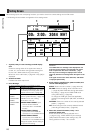
When the Program/Preset system is selected, the A/PROG
bus source selector button corresponding to the source
used for the transition pattern and output from a PGM
connector is necessarily lighted or ashes. Thus, an input
source that you want to display next can be selected only
with the B/PRESET bus source selector buttons.
For more information about the input source selection
operation, see page 33.
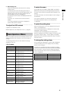
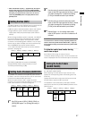
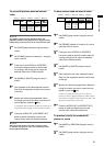
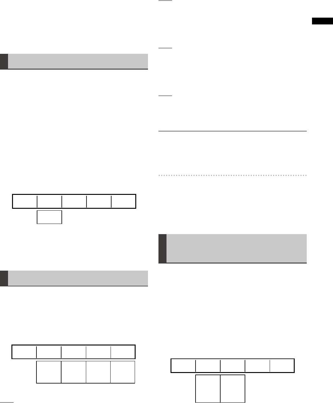
Rotary 1 Rotary 2 Rotary 3 Rotary 4 Rotary 5
AB
PRG/PRE
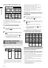
TYPEBUS
AB
Set [TYPE] to [AB] (AB bus system) or [PRG/PRE]
(Program/Preset system) using the rotary 2 control.
The factory default setting is [AB].
Setting Audio Channels [AUDIO CH]
The [AUDIO CH] submenu of the [SETUP] menu is used
to select L channel or R channel of this unit for each audio
channel of the selected SDI input source.
When the system format is HD (
page 19), audio
channels 1 to 8 can be assigned. When the system format
is SD, audio channels 1 to 4 can be assigned.
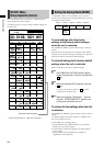
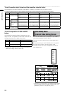
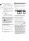
Rotary 1 Rotary 2 Rotary 3 Rotary 4 Rotary 5
1-8 (1-4) 1-8 (1-4) OFF
ON
SDI1
SDI2
SDI3
SDI4
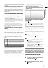
CH
CHAUDIO
SDI1 1 2 ON
L-CH R-CH OSD
1
Set [CH] to one of [SDI1], [SDI2], [SDI3], or
[SDI4] (SDI inputs 1 to 4) using the rotary 2
control.
2
Use the rotary 3 control to select the audio
input (of the SDI input selected in Step 1) which
you want to assign the L channel by setting
[L-CH] to the desired audio input number.
3
Use the rotary 4 control to select the audio
input (of the SDI input selected in Step 1) which
you want to assign the R channel by setting
[R-CH] to the desired audio input number.
4
Repeat Steps 1 to 3 to assign each audio
input of SDI inputs 1 to 4 to the L channel or R
channel.
NOTE
The set channel is stored in memory separately between the
cases in which the system format is SD and HD ( page 19),
and is called according to the format when the system format
is changed.
To hide the audio level meter during
multi-view output
Set [OSD] to [OFF] using the rotary 5 control.
The factory default setting is [ON], in which the audio level
meter is displayed when the multi-view output is monitored.
Setting the Audio Faders
[AUDIO FADER]
The audio input level is adjusted with the SOURCE 1/5, 2/6,
3/7, 4/8 faders (audio faders).
When adjusting the audio level of input sources 5 to 8,
operate the corresponding fader while holding down the
SHIFT key.
Operate the AUX fader to adjust the AUX input level and
the MIC fader to adjust the MIC input level.
The operation of the audio faders, AUX fader, and MIC
fader can be set from the [AUDIO FADER] submenu of the
[SETUP] menu.
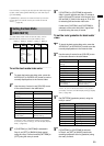
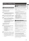
Rotary 1 Rotary 2 Rotary 3 Rotary 4 Rotary 5
PAIR
SEPA.
CP PAIR
BUS SEP1
BUS SEP2
12 PAIR
12 SEPA.
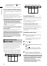
FADER
SOURCEAUDIO
BUS SEP1
PAIR
AUX/MIC