


14
G/L
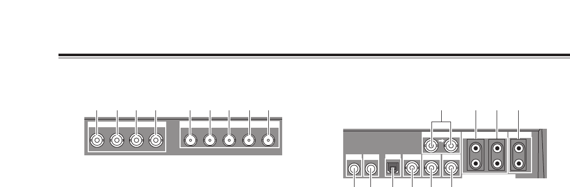
MIC
PHONE
USB
ADV-REF
PREVIEW
GPI
AUX IN
1
2
L
R
L
R
AUDIO OUT 2
EDITOR
589 :
1 2 3 4 6 7
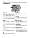
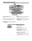
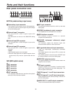
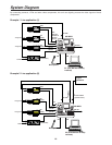
MIC input connector
This connector can be set to MIC or AUX 2 on the initial
setting page.
1
2
PHONE (headphone) output connector
The headphones are connected to this connector.
3
USB interface connector
This connector is used to connect to a personal
computer and download files.
4
5
ADV-REF (advanced reference) output
connector
This connector outputs the reference signal with
advanced vertical phase for source input uses.
8
AUX IN (spare) 1 L and R input connectors
AND
9
AUX IN (spare) 2 L and R input connectors
These connectors can be used by making a selection on
the initial setting page.
:
AUDIO OUT 2 L and R output connectors
These are unbalanced audio output connectors.
G/L (genlock reference) input connectors
These are loop-through, automatically terminated
connectors.
They supply signals to the source VTR or camera and
initiate genlock.
They enable genlock for the G/L input or EXTKEY input
by making a selection on the initial setting page.
6
PREVIEW output connector
The signals selected by the preview selector button are
output from this connector.
7
GPI input connector
A trigger is applied and a transition is enabled for ME,
DSK or fade as selected on the initial setting page. The
effect is applied 3 frames later.
Parts and their functions
KEY
EXT IN
Y
B
P
R
P
IN1 IN2 IN3 IN4 OUT
SDI
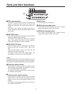
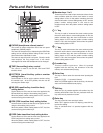
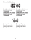
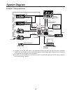
EXT IN (external key input area)
SDI (SDI option area)
1 2 3 4 5 6 7 8 9
External key input connector
This connector can be used for key or DSK applications.
It can also be used for genlock signal using the settings
on the initial setting page.
1
2
External input Y connector
The cross point EXT or DSK Y signal is input to this
connector.
The DSK source can be set on the DSK/FADE setting
page.
3
External input PB connector
The cross point EXT or DSK PB signal is input to this
connector.
9
OUT connector
The connectors listed above are used when the optional
board (AG-YA70) has been installed.
4
External input PR connector
The cross point EXT or DSK PR signal is input to this
connector.
<Notes>
≥ Non-standard signals are not accepted.
≥ Since the input signals do not pass through the frame
synchronizers, they must be synchronized with this
unit.
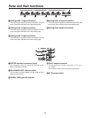
5
6
IN1 connector
IN2 connector
7
IN3 connector
8
IN4 connector
Rear panel connection area