17
External interfaces
This unit comes with three connectors to support four
external interfaces: a GPI input connector, RS-422A/RS-232
(9-pin) connector and a Tally output connector. Select the
connector that suits the editing controller model used.
∫ GPI (general purpose interface)
This enables the use of auto takes with the GPI output of
the external controller. At the fall of the GPI signal, wipe/mix
set on the panel or DSK or Fade is executed.
∫ RS-422A
This enables the AG-A850 external editing controller to be
connected to the unit and the VTR to be controlled from a
remote location.
≥ Functions that can be controlled from the AG-A850
±Wipe settings
±Mixing
±Auto take time and auto fade time settings
±Downstream key fade-in and fade-out
±Cross point source 1/source 2 (source 2/source 3
or source 3/source 4) switching
(Cross mode switching is performed by the RS-
422A/RS-232C selector switch on the rear panel.
Support for the editing controller is shown below.)
≥ Connections
1) Set the RS-422A/RS-232C selector switch to
“RS-422A.”
2) Connect the connecting cable from the AG-A850
to the editing controller connector on this unit.
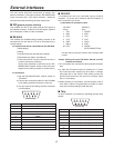
3) The pin layout of the editing controller connector
is shown below.
∫ RS-232C
This enables the unit to be controlled using a personal
computer. All of the unit’s functions with the exception of
AUX 1 and AUX 2 can be set.
≥ Connection of conversion cable
RS-232C AG-MX70
25-pin 9-pin
1 TXD 1 SPARE
3 RXD 2 RXD
4 RTS 3 TXD
5 CTS 4 DTR
6 DSR 5 SIG.G
7 SIG.G 6 DSR
20 DTR 9 SPARE
[DCE CONNECTION]
Use the above conversion with the 9-pin straight cable
as well.
<Notes> Editing using the RS-422A, RS-232 and GPI
interface connectors
≥ The commands are received and then executed 3 frames
later.
≥ If, while the 3D optional board is installed, the 1-Frame
Dly mode has been selected by the system 1 settings
(see page 56) on the “Setup” initial setting screen, the
pictures and sound from the source are always output
with a 1-frame delay.
≥ When selecting a DVE pattern, set the transition time to
more than 2 frames. No guarantees are made for frame
accuracy if the time setting is lower than this.
∫ Tally
An open connector is provided for outputting the tally lamp
signals.
Pin No
1
2
3
4
5
6
7
8
9
Signal
FRAME GROUND
TRANSMIT A
RECEIVE B
RECEIVE COMMON
SPARE
TRANSMIT COMMON
TRANSMIT B
RECEIVE A
FRAME GROUND
5 4 3 2 1
9 8 7 6
Connector (9P)
5 4 3 2 1
9 8 7 6
Connector (9P)
Pin No
1
2
3
4
5
6
7
8
9
Signal
Output for cross point 1
Output for cross point 2
Output for cross point 3
Output for cross point 4
Output for cross point 5
Output for cross point 6
Output for cross point 7
Output for cross point 8 or EXT
GND


