


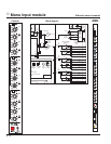
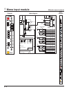
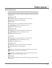
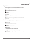

Rear panel features
Direct out 1/4" TRS jack
The input channel's signal is available at this output jack.The D.O.signal is derived
Post-fader (post-eq and post-mute).This output jack is ground-compensated.
Insert points
Separate 1/4" TRS jacks provide the facilities for inserting an external signal processor into
the signal path of the input channel.
Insert send
This jack serves as an output for connection to the input of a signal processor.
The signal is derived after the mic preamp and HPF but before the eq section.Plugging a 1/4"
TRS plug into this jack does not break the signal flow of the channel.This output jack is
ground-compensated.
Insert return
The output of a signal processor is fed to this jack. It can accept a balanced or
unbalanced signal and is located pre-eq. Plugging a 1/4" TRS plug into this jack breaks the
normal signal flow of the channel.
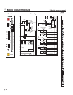
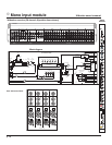
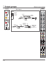
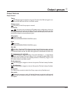
Passive splitter features
The input of the X-Monitor includes a simple passive splitter for running input signals par-
allel to another desk,typically a front-of-house console.In most cases this can eliminate the
need for a separate splitter box.
Pin 1 lift
When this button is depressed, the XLR Mic-In and Splitter-Out Pin-1 connection is
isolated from the chassis ground of the console.The Pin-1connection is maintained between
the two jacks,but is isolated from the mixer ground.
NOTE: When the Pin-1 Lift switch is depressed, the phantom power (+48V) from the X-
Monitor won’t function for that XLR input. Phantom power needs the Pin-1 ground con-
nection for the return path for the +48 volts.
Balanced Input XLR connector—Bal In
This balanced female XLR (Pin 2 Hot) accepts a low-impedance microphone signal,or
a line-level signal, depending on position of the LINE switch on the front panel.
Splitter Out
This male XLR allows the channel input to be patched to another piece of audio
equipment, such as a front-of-house console. It is simply a parallel connection of whatever
is plugged into the Input XLR.
NOTE:All pins (1,2,3) are wired in parallel with the corresponding pins of the female XLR.
The Pin-1 Lift does NOT disconnect any of these parallel connections.
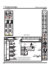
T= OUT
+
R= G COMP
S= GND
T= OUT
+
R= G COMP
S= GND
p.19
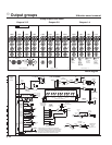
Mono input module
1