


4
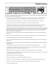
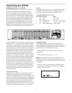
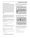
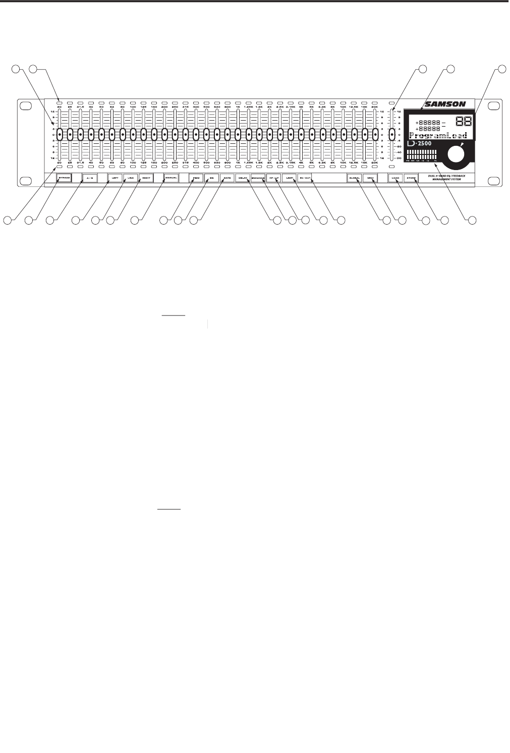
1 FADER
– 45mm LED fader for each of the 31 frequency
bands, which can be software set for +/- 12 dB or +/- 6 dB
,
or
+/- 3 dB
of cut and boost.
2 ABOVE NULL LED
– Red LED indicating the fader is
below the null
(matching)
point.
Note:
the null point
is the exact location where the fader's
physical
postion
physical postion physical
matches the level of the digital filter.)
3 MASTER FADER
- 45mm LED fader for the Main Output
level, which can be software set for +/- 12 dB
or +/- 3 dB
or +/- 6 dB of cut and boost, as well as
+12/- 120 dB
or
+
6
/- 120
dB
or +3 dB
/- 120
.
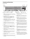
4 LCD DISPLAY
– Backlit display that shows the various
parameters under control by the operating system.
5 DATA WHEEL
– Rotary encoder for entering parameter
values.
6 BELOW NULL LED
- Green LED indicating the fader is
above the null (matching) point.
Note:
the null point is the
exact location where the fader's
physical
postion matches
physical postion matches physical
the level of the digital filter.)
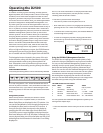
7 BYPASS switch
– When the red LED is on, the digital
equalizer, as well as all the on-board digital processing
effects, are defeated.
8 A / B switch
– Used to switch between the your actual
modified program, to the last program that has been
loaded or stored into memory.
9 LEFT switch
– Assigns the Left (CH1) digital equalizer to
the physical controls.
10 LINK switch
– Used to control the left and right (CH1 and
CH2) equalizer simultaneously with the one set of physi-
cal controls.
Controls and Functions
Front Panel Layout
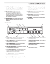
11 RIGHT switch
- Assigns the Right (CH1) equalizer
to the physical controls.
12 MANUAL switch
– When engaged, the left and
right equalizers are linked to the physical faders.
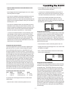
13 FBM switch
– Used to access the automatic
Feedback control parameters. When selected, the
amber LED will illuminate and the associated val-
ues will be displayed in the LCD window.
14 EQ switch
-- When engaged, the amber LED will
illuminate indicating that the EQ parameters are
under control and displayed in the LCD window.
15 GATE switch
- Used to access the automatic GATE
control parameters. When selected, the amber LED
will illuminate and the associated values for the
digital noise gate will be displayed in the LCD win-
dow.
16 DELAY switch
- When engaged, the amber LED will
illuminate indicating that the DELAY parameters
are under control and displayed in the LCD win-
dow.
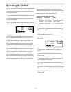
17 ENHANCER switch
- When engaged, the amber
LED will illuminate indicating that the DELAY
parameters are under control and displayed in the
LCD window.
18 HP / LP switch
– LED switch used to access the
automatic HI PASS and LOW PASS control param-
eters. When selected, the amber LED will illuminate
and the associated values for the high and low pass
filters will be displayed in the LCD window.