


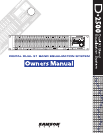
5
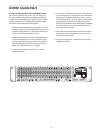
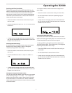
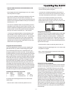
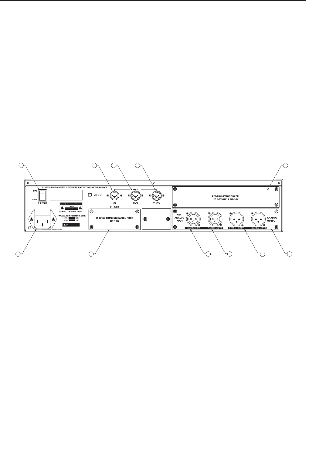
A POWER SWITCH
– When set to the ON position the
D2500 is powered up and ready for operation.
B MIDI IN DIN connector
– The D2500 receives standard, or
system exclusive, MIDI data here.
C MIDI OUT DIN connector
- The D2500 transmits stan-
dard, or system exclusive, MIDI data here.
D MIDI THRU DIN connector
- The D2500 passes standard,
or system exclusive, MIDI data here.
E I/O Accessory Blank Panel
– removable blanking panel
accesses option bay for adding additional Analog-to
Digital or Digital Input/Output boards.
F
AC input fuseholder
- Connect the supplied heavy
gauge 3-pin “IEC” power cable here.
G
D-NET Accessory Blank Panel
– removable blanking
panel accesses option bay for adding the D-NET interface
card for control multiple D class units.
Controls and Functions
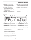
Rear Panel Layout
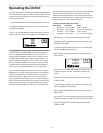
H
CH1 Balanced XLR jack input
- Electronically bal-
anced XLR jack input.
I
CH2 Balanced XLR jack input
- Electronically bal-
anced XLR jack input.
J
CH1 Balanced XLR jack output
- Electronically
balanced XLR jack output.
K
CH2 Balanced XLR jack output
K CH2 Balanced XLR jack outputK
- Electronically
balanced XLR jack output.
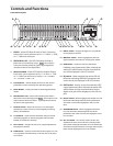
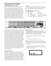
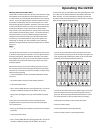
19 LIMITER switch
– This switch is used to page
through the LIMITER parameters. When selected,
the amber LED will illuminate and the LIMITER
parameters will be displayed in the LCD window.
20 IN / OUT switch
– The LED switch is used
to engage the EQ, FEEDBACK, GATE, DELAY,
ENHANCER and LIMITER effects. When one of
the above effects switch is selected, (for example
FEEDBACK), that effect is turned on when the IN /
OUT amber LED is illuminated.
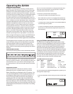
21 GLOBAL switch
– When engaged, the red LED will
illuminate indicating access to the unit's GLOBAL
parameters.
22 MIDI switch
- This switch is used to page through
the MIDI parameters. When selected, the red LED
will illuminate and the MIDI parameters will be dis-
played in the LCD window.
23 LOAD switch
– Used to load one of the 100 pro-
grams from the internal memory.
24 STORE switch
- Used to store one of the 100 pro-
grams into the internal memory.
25 Level Meter
- Twelve segment LED meter display
the input level.
THIS DEVICE COMPLIES WITH PART 15 OF THE FCC RULES
CLASS B. OPERATION IS SUBJECT TO THE FOLLOWING TWO
CONDITIONS: (1) THIS DEVICE MUST NOT CAUSE HARMFUL
INTERFERENCE
, AND (2) THIS DEVICE MUST ACCEPT ANY
INTERFERENCE RECEIVED INCLUDING INTERFERENCE THAT
MAY C
AUSE UNDESIRED OPERATION.