


21
TIPS FOR ACHIEVING OPTIMUM PERFORMANCE
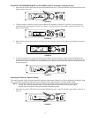
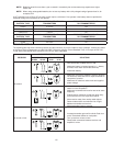
Maintain a line of sight between the transmitter and receiver antennas.
Avoid placing transmitter and receiver where metal or other dense materials may be present.
Avoid placing the receiver near computers or other RF generating equipment such as CD players, DAT machines, and
digital signal processors.
Avoid placing the receiver in the bottom of an equipment rack unless the antennas are remotely located.
Point the receiver antenna tips away from each other at a 45° angle, and keep them away from large metal objects.
Do not obstruct the receiver antennas.
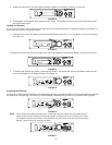
Use the proper cable when remotely locating receiver antennas. For best performance, use Shure UA825 or UA850
low loss coaxial antenna cable, or 50 ohm low loss cable such as RG-8U.
For remote antenna placement, use Shure UA820WB 1/2 Wave Antenna and UA830WB Active Remote Antenna Kits,
along with Shure UA844WB Antenna Distribution System.
Mount diversity antennas at least 1/4 wave apart. This can be achieved by remote placement of one or both 1/2 wave
antennas using Shure UA825, UA850, or UA8100 low loss coaxial cable and a Shure UA830WB Active Remote
Antenna Kit in conjunction with a Shure Antenna Distribution System. For multiple system installations, use the Shure
UA844WB Antenna/Power Distribution System.
Try to maintain a distance of at least 5 meters (15 ft) between the transmitter and receiver.
SPECIFICATIONS
NOTE: For a list of compatible frequencies that are usable in your area, refer to the supplied frequency
supplement.
RF Carrier Frequency Range
554.000 to 865.000 MHz (Available frequencies depend on the applicable regulations in the country where the system is
used). Refer to the frequency supplement supplied with the system.
Effective Range
100 m (300 ft.) under optimal conditions
NOTE:
Actual working range depends on RF signal absorption, reection, and interference
Audio Frequency Response
25 to 15,000 Hz, ±2 dB
NOTE: Overall system frequency response depends on the microphone element.
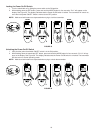
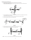
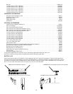
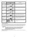
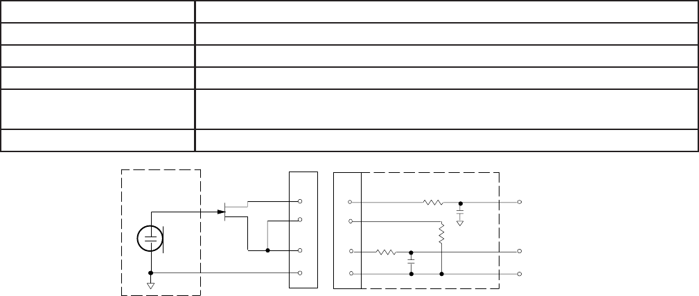
ULX1 Transmitter Input (Figure 54)
Connector: TA4F
Input Conguration: Unbalanced, active
Actual Impedance:
18 kΩ with lavalier microphone 1 MΩ with instrument cable
Maximum Input Level:
10 Vp–p (12 dBV) for 1% THD at minimum gain setting using 1 kHz signal.
TA4F Connector Pin Assign-
ments:
Pin 1: Tied to Ground Pin 2: Tied to +5 V Pin 3: Tied to Audio Pin 4: Tied thru
20kΩ Resistor to Ground. (On instrument adapter cable, Pin 4 oats)
Voltage for Remote Power: +5 V supplied to microphone cartridge
FIGURE 54
•
•
•
•
•
•
•
•
•
•
27 pF
20K :
27 pF
+5 V
AUDIO
GROUND
ULX1 MIC JACK BOARD
2
1
4
500 :
500 :
MICROPHONE
ELEMENT
3
2
1
3
4
NOTE: LAVALIER MIC TIES PINS 3 AND 4 TOGETHER; THE GUITAR CABLE DOES NOT.