


9
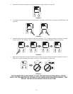
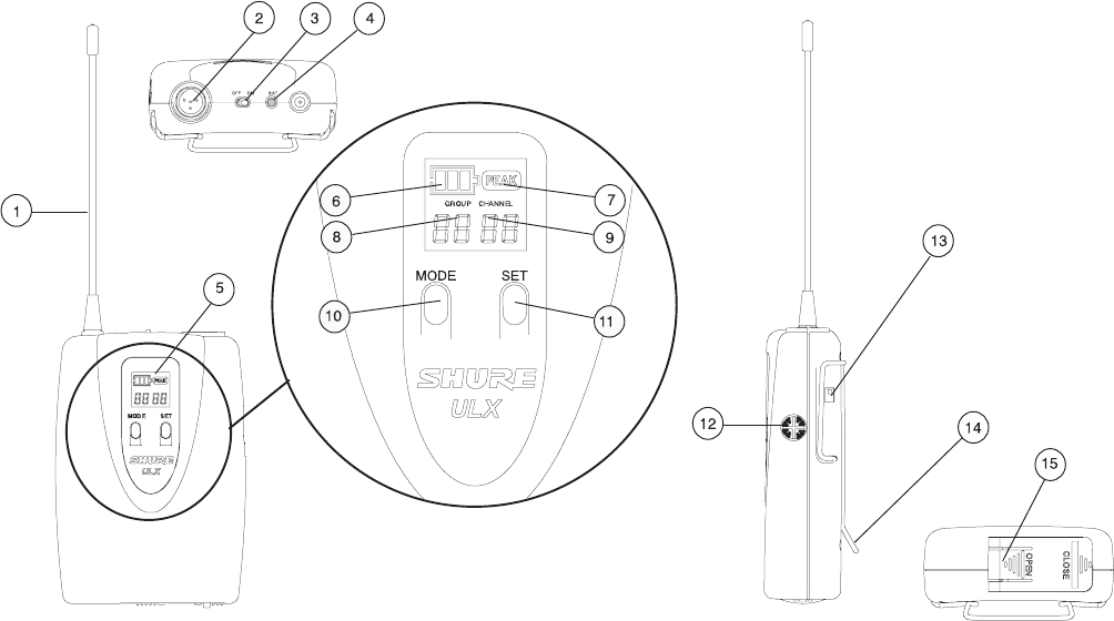
ULX1 TRANSMITTER FEATURES AND CONTROLS
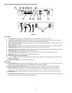
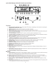
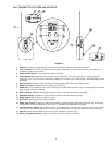
FIGURE 18
Antenna. A exible 1/4 wave antenna is permanently attached to the top of the ULX1 transmitter.
Input Connector. This TA4F miniature four-pin connector mates with a variety of Shure lavalier, instrument and
headset microphones and cables.
Power ON/OFF Switch. Turns transmitter power on and off.
Power/Battery LED. When the Power switch is in the ON position, this LED will glow green, indicating that the
transmitter is on. This LED will turn red when the battery is low. Refer to the “Checking the Transmitter Battery Power”
paragraph.
Display Window. Displays Group and Channel setting, battery power level, and PEAK indicator.
Battery Level Icon. Indicates amount of battery life remaining.
PEAK Icon. This icon appears when audio input signal overloads the transmitter. The icon is displayed for 2 seconds
after the input overload is detected.
GROUP Display. Indicates the frequency Group number in which the transmitter is operating.
CHANNEL Display. Indicates the current Channel number within the frequency Group.
MODE Button. Selects Group or Channel mode.
SET Button. Changes Group or Channel setting.
Audio Gain Control. Changes the audio level sensitivity to accommodate various sound sources (e.g. loud singing,
soft speaking, or musical instrument). Refer to the “Transmitter Gain Adjustment” paragraph.
Input Attenuation Switch. Selects either 0 dB or –20 dB attenuation. Use the 0 dB position for voice and low output
instruments. Use the 20 dB pad position for high output instruments such as electric guitars with active electronics.
Belt Clip. Allows the transmitter to be worn on a belt, waistband, or guitar strap.
Battery Compartment Cover. Hinged cover opens to provide access to 9V battery.
1.
2.
3.
4.
5.
6.
7.
8.
9.
10.
11.
12.
13.
14.
15.