


5
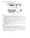
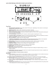
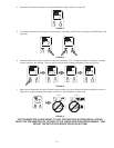
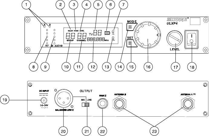
ULXP4 PROFESSIONAL RECEIVER FEATURES AND CONTROLS
FIGURE 3
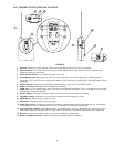
Front Panel
Receiving Antenna Indicators. One of these amber LEDs will glow , depending on which antenna is receiving the
strongest Radio Frequency (RF) signal.
SQUELCH Indicator. Appears when the Squelch Level Mode is selected.
SCAN Indicator. Appears when the receiver is scanning for an open Group or Channel.
Volume Level Warning Indicator. Indicates a discrepancy between the Volume control knob position and the previ-
ously locked Volume Level setting.
TV Channel Display. Indicates the UHF TV channel in which the system is operating (U.S. only).
Transmitter Battery Life Indicator. Displays the remaining transmitter battery life when the transmitter is turned on.
Volume Lock Indicator. Appears after the Volume level setting has been locked.
RF Level Indicators. Indicate received RF signal strength.
“TX Audio” Level Indicators. Indicate transmitted (TX) audio signal strength. Green indicates normal operation.
Amber indicates approaching overload condition. Red indicates excessive audio levels.
GROUP Display. Indicates the pre-selected Frequency Group number in which the system is operating.
CHANNEL Display. Indicates the current Channel number within the Frequency Group.
FREQUENCY Display. Indicates the current frequency in megahertz (MHz).
Frequency Lock Indicator. Appears when the Frequency has been locked.
MODE Button. Press this button to step through the display menu.
SET Button. Saves the altered setting.
Display Control Knob. Rotate this knob to change the Group/Channel settings, the Squelch setting, or to scan a
Group or Channel.
Level Control. Adjusts the receiver audio output level to match the required input levels of a mixer or amplier. Nor-
mally, this control is set fully clockwise.
Power On/Off Switch. Turns the receiver on and off.
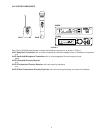
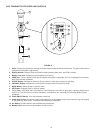
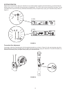
Rear Panel
Power Connector. Accepts power from the supplied AC adapter, or from any ltered 14–18 Vdc (550 mA minimum)
supply. It also accepts DC power from a Shure UA844 Antenna Distribution System.
Output Connector (XLR balanced Low Z). Provides balanced low–impedance mic level or line level output.
Mic/Line Switch. Selects output of XLR balanced Low Z connector. It can be set for microphone (–27 dBV) or line
level (+4.3 dBV). This switch does not affect the output of the unbalanced 1/4 inch phone jack.
Output Connector (High Z Unbalanced 1/4 inch Phone Jack). Provides unbalanced high impedance auxiliary
level output.
Antenna Input Connectors. BNC–type connectors provide connection to the supplied antennas. They also provide
12 Vdc output power for use with remotely located antennas.
1.
2.
3.
4.
5.
6.
7.
8.
9.
10.
11.
12.
13.
14.
15.
16.
17.
18.
19.
20.
21.
22.
23.