


10 TASCAM FW-1082 Owner’s Manual
2 – Parts of the FW-1082
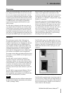
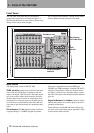
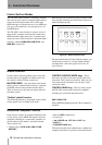
Front Panel
The FW-1082 front panel may be conveniently
grouped into logical areas as shown in Figure 2.1.
Note that the functions of some of these controls may
change as the control mode changes.
See “Control Surface Modes” on page 16 for details
of these different modes and how to set them:
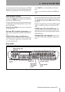
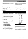
Input section
The analog input section of the FW-1082.
TRIM controls Analog level controls for the input
level of the mic (XLR) input 1 through 4, and line
inputs 1 through 8. Their function is the same regard-
less of the control surface mode selected. Note that
the best signal-to-noise ratios are achieved by maxi-
mizing the level of analog inputs at the A/D convert-
ers. For the mic and line inputs of the FW-1082, the
trim controls provide the means for optimizing these
levels.
OL indicators The OL indicators light to indicate
a signal peaking at –2.5dBFS or higher by default
(this level is adjustable between 0.0 dBFS and
5.0 dBFS, in 0.5 dB increments, using the FW-1082’s
software Control Panel). When one of these indica-
tors lights, it indicates an overloaded input—reduce
the level of the input to the channel until the indicator
goes out.
Signal indicators The SIGNAL indicators light to
indicate the presence of an audio signal at the corre-
sponding analog input.
These indicators and the
OL indicators indicate sig-
nal levels to the eight analog inputs regardless of the
control surface mode selected.
Figure 2.1: Front panel features
Input section
Channel controls
Encoders and
controls
d
Monitoring
and indicators
Mode
controls
DAW transport
controls