


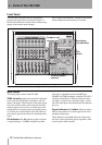

2 – Parts of the FW-1082
14 TASCAM FW-1082 Owner’s Manual
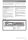
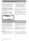
Line inputs and inserts
LINE IN jacks Balanced line level (+4 dBu) ¼"
TRS (tip = hot, ring = cold, sleeve = ground) analog
inputs. Inputs 1 through 4 are wired in parallel with
their associated mic inputs. Only connect a line
source or a microphone to these pairs of inputs. Do
not connect a line source and a microphone to the
same input pair at the same time.
INSERT 1 & 2 Individual channel inserts. These
are ¼" TRS (tip = send, ring = receive, sleeve =
ground) jacks which allow you to insert an external
processor, such as an analog compressor, into the sig-
nal chain for inputs 1 and 2 (mic or line). The insert
point is placed between the input (after the mic/line
trim) and the analog-to-digital converter. A standard
insert’Y’-cable with a TRS plug is required. Check
with your music retailer.
GUITAR/LINE switch Affects LINE IN 8 only.
When this is set to
GUITAR, the input impedance
then matches that of an electric guitar or passive bass.
For all other instruments, leave this in the
LINE posi-
tion.
Mic inputs and phantom power switch
MIC (1 through 4) These XLR connectors (1 =
ground, 2 = hot, 3 = cold) are connected to high-qual-
ity internal microphone pre-amplifiers.
These connectors are wired in parallel with the corre-
spondingly-numbered
LINE IN jacks. Only connect a
line source or a microphone to these pairs of inputs.
Do not connect a line source and a microphone to the
same input pair at the same time.
PHANTOM (+48V) switch Use this to switch
+48V phantom power to the microphone jacks.
WARNING
Microphones should not be connected to or discon-
nected from the FW-1082 with phantom power
switched on.
Unbalanced dynamic microphones should never be con-
nected to phantom-powered connectors.
Foot switch jack (FOOT SW)
Accommodates a standard momentary foot switch
through a ¼" jack.
FireWire (IEEE.1394) ports Use one of these
ports to connect the FW-1082 to the host computer,
providing audio, MIDI and control surface communi-
cation. Either port may be used to connect the FW-
1082 to your computer
COAXIAL Digital audio I/O (IN and OUT)
S/PDIF coaxial digital input and output using RCA
(pin) connectors.
You can configure these on the software Control
Panel to act as additional inputs and outputs.
MIDI I/O
Two MIDI IN and two MIDI OUT connectors allow
you to hook up MIDI controllers, etc. as well as
external tone generator modules, etc.
Monitoring and phones
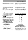
PHONES jack Headphone level output from a ste-
reo 1/4” jack.
MONITOR (BAL) Outputs L & R Two bal-
anced +4 dBU line-level ouputs on ¼” TRS jacks (tip
= hot, ring = cold, sleeve = ground).