


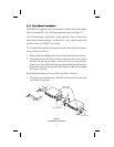
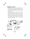

2. Install the previously removed screws. Insert an additional screw
(provided in the parts pack) into the remaining holes. Tighten all
screws securely.
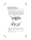
3. Place the two assemblies side-by-side with the mid brackets to
-
gether. (The left bracket should fit above the right so that the
countersinks are visible). Install 4 flat-head screws (Item #5) and
tighten them securely.
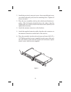
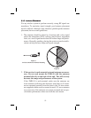
4. Attach the antenna connectors to the brackets.
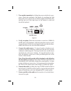
5. Attach the supplied extension cables from the rack connectors to
the antenna connections on the back of the receiver.
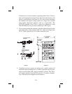
6. Place the assembly into the rack enclosure and insert 4 #10-32 x
3/8” Phillips pan head screws (supplied) in eachcorner of the rack
ears and secure to the enclosure. Some rack enclosures require
metric screws which are not supplied.
-8-
F
M
R
-
1
0
D
i
v
e
r
s
i
t
y
A
U
D
I
O
C
h
a
n
n
e
l
F
M
R
-
1
0
D
i
v
e
r
s
i
t
y
A
U
D
I
O
C
h
a
n
n
e
l
Figure 4