


3. Detailed Setup Instructions
3.1 FMR-10 Receiver Setup & OperationReceiver Setup & Operation
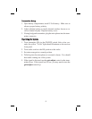
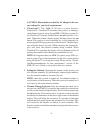
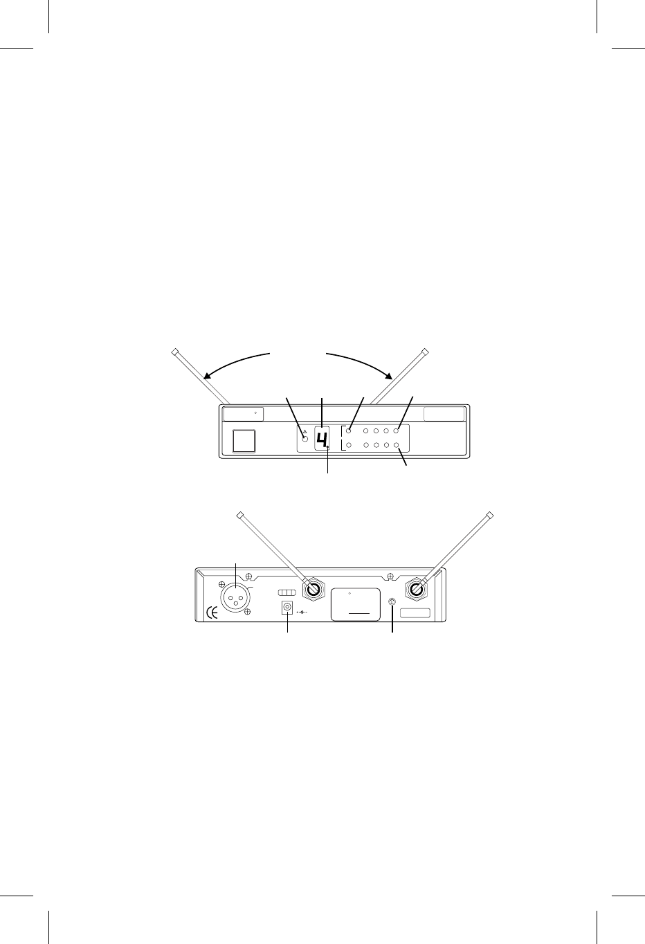
1. Place the receiver where there is a clear line of sight to the area
where the transmitter will be used.
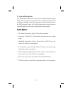
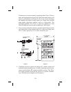
2. Attach either the supplied 1/4-wave antennas or two remotely
mounted antennas to the antenna connectors on the rear panel of the
FMR-10. Be sure and tightenthe connectors securely. If the supplied
1/4-wave antennas are used, they must be oriented at a 90
o
angle as
shown in Figure 2. Unlike other diversity wireless systems, two
antennas are required for the FMR-10 to operate correctly.
3.
Connect the power supply cord to the receiver. Plug the power
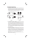
supply into an AC outlet. Confirm that the receiver is ON by
checking for thelighted channel displayand diversity led’son the
front panel.
NOTE: Upon power-up, the receiver will return to the channel it
was set to when it was turned off.
-4-
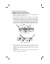
CHANNEL
DISPLAY
CHANNEL
SET
BUTTON
SET ANTENNAS
AT 90 DEGREES
Channel
Diversity
Audio
RF
A
B
1234
-20 -10 0 +3
DIVERSITY
LIGHTS
RF
METER
AUDIO METER
LOCK OUT INDICATOR
Telex
R
CLEAR
SCAN
TM
FMR-10
Made
in
U.S.A.
Balanced
Mic Level
Output
Power
12-15 V AC/DC
700 mA
Squelch
llll llll llll
llll lllllll llll
BALANCED
AUDIO
OUTPUT
POWER
JACK
SQUELCH
CONTROL
Antenna Antenna
Telex
FMR-10
R
F
C
C
Tested to Comply
with FCC Standards
Canada
Patent Pending
Figure 1 FMR-10 Front View
Figure 2 FMR-10 Rear View