


VAV-PRC003-EN 19
Application
Considerations
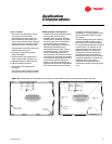
• When the average glass plus wall heat
loss is less than 250 Btuh/linear foot,
the slot diffuser may be located in
the center of the room with one or
more slots blowing toward the
perimeter wall.
• With glass and wall heat loss between
250 and 450 Btuh/linear foot, diffusers
should be positioned to blow toward
the window and the perimeter wall with
a collision velocity of 75 to 150 fpm. If
using a continuous glass design,
position diffusers every four feet.
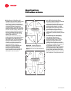
• If heat loss exceeds 450 Btuh/linear
foot, radiation or floor mounted heated
air will be required to offset the high
wall heat loss.
Step 7. Air Diffuser Selection and
Placement
Supply Diffusers
Many types of supply air diffusers are
used in variable air volume systems.
Performance, and ultimately space
comfort, can vary greatly depending on
the diffuser selected. Although
constant-volume diffusers will provide
air to the space at full cfm, as air
volume delivered to the space
decreases, so does performance.
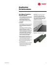
Linear slot diffusers are recommended
for most VAV systems.
Linear supply air slot diffusers are
designed to properly mix variable air
delivery of both heated and cooled air.
Linear slot diffusers supply conditioned
air which “hugs” the ceiling rather than
“dumps” air downward on the
occupants. This airflow characteristic is
known as the “coanda effect”. The
throw and aspiration characteristics of
slot diffusers help to evenly distribute
the air throughout the room or space.
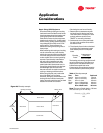
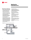
Locate linear slot diffusers in the center
of the room with the discharge air
pattern perpendicular to a perimeter
wall. To maximize diffuser
performance, placement in which air
discharge patterns converge at right
angles should be avoided. (See Diffuser
section of the VariTrane catalog (VAV-
PRC008-EN) for additional diffuser
placement and performance
recommendations.)
The throw characteristics of diffusers is
well-documented. Slot diffusers should
be positioned so that the velocity of the
air striking an obstruction (such as a
wall or column) is 75 feet per minute
(fpm) or less. If airstreams from two
diffusers collide, the collision velocity
should not exceed 150 fpm. Higher
collision velocities result in
uncomfortable drafts in the lower levels
of the room.
In heating applications, linear slot
diffusers must be placed to offset heat
loss and prevent downdraft problems
along perimeter walls. The following
techniques have been proven by test
and experience:
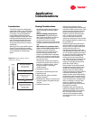
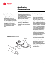
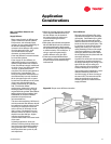
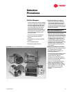
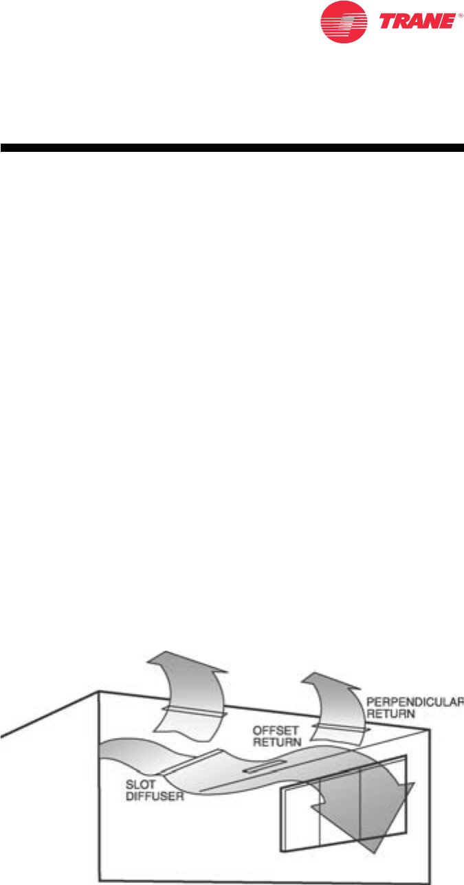
Figure 22. Proper return diffuser orientation
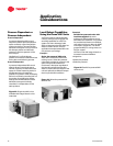
Return Diffusers
Slot-style return diffusers offer some
acoustical advantages over perforated
grille styles. Perforated drop-in grilles
typically offer little attenuation effect
and thus allow sound in the plenum to
break out into the occupied space. This
is a problem in areas near the unitary
heating and cooling unit. Improved
ceiling aesthetics is also an advantage
of slot return diffusers in jobs where
slot supply diffusers are used. Within
the occupied space, they blend with the
slot supply diffusers.
A general rule of thumb is for the return
air openings to equal the total area of
the supply openings. If the ceiling is not
tight, such as a drop-in ceiling, the
return openings can be reduced by up
to 50% of the supply air openings.
To promote good air distribution, return
diffusers should be positioned to
minimize supply air short-circuiting to
the return slot. The returns should be
either perpendicular to the supply
airflow or parallel and offset from the
supply diffusers.