


VAV-PRC003-EN 31
Electrical Data
and Connections
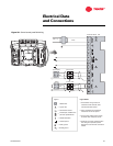
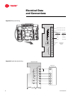
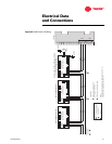
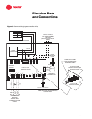
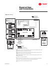
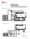
Figure 35. UCM Comm Link Wiring
VariTrac
Ter mination Board TB2
Sta
tic
Press
u
re
Po
rt
+
VOUT
–
Air S
u
p
p
ly
T
e
m
p
.
Sen
so
r
Pres
s
u
re
T
ra
nsduce
r
1
10
11
12
13
14
15
9
8
7
6
5
4
3
2
+
–
J3
R
G
BK
S
GRNYEL
ACT
24V
GND
ZONE
BIP
GND
GND
TB3–6
A/CO2
SET
J1
J10
TB1–1
TB2–6
TB3–1
TB3–2
TB3–3
TB3–5
J11
J9
J7
J8
TB2–2
TB2–3
TB2–5
TB2–4
TB2–1
+
+
+
–
–
–
1
PRESS
1
D.D.C.\U.C.M.
CONTROL BOARD
TB4–1
TB1–2
Communication Sensor/Bypass Control
Assembly Address #33
ADDRESS
SWITCH
COMM 5
COMM 4
Splice
2
Splice
To Zone Dampers
3 through 24
J3
S
GRNYEL
ACT
24V
GND
ZONE
BIP
GND
GND
TB3–6
A/CO2
SET
J1
J10
TB1–1
TB2–6
TB3–1
TB3–2
TB3–3
TB3–5
J11
J9
J7
J8
TB2–2
TB2–3
TB2–5
TB2–4
TB2–1
+
+
+
–
–
–
1
PRESS
1
D.D.C.\U.C.M.
CONTROL BOARD
TB4–1
TB1–2
ADDRESS
SWITCH
J3
S
GRNYEL
ACT
24V
GND
ZONE
BIP
GND
GND
TB3–6
A/CO2
SET
J1
J10
TB1–1
TB2–6
TB3–1
TB3–2
TB3–3
TB3–5
J11
J9
J7
J8
TB2–2
TB2–3
TB2–5
TB2–4
TB2–1
+
+
+
–
–
–
1
PRESS
1
D.D.C.\U.C.M.
CONTROL BOARD
TB4–1
TB1–2
ADDRESS
SWITCH
Zone UCM Address #2 Zone UCM Address #1
Figure note
Shielded ground
Twisted pair, shielded wire
per Trane specifications
Legend
=
=
=
Figure Notes:
Shield must be spliced with other
communication link shields.
Shield must be cut back and taped.
Notes:
The UCM order in this drawing is for demonstration purposes only.
No specific order is required on the Comm link.
2
1
2
1
2