


VAV-PRC003-EN 33
Electrical Data
and Connections
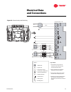
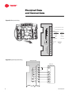
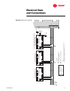
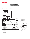
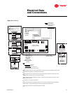
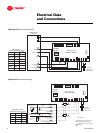
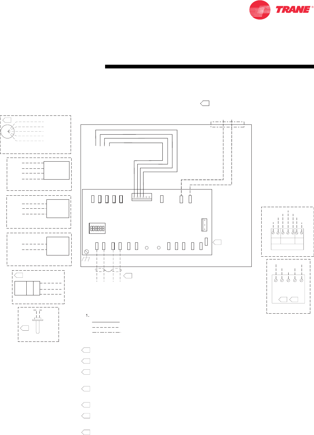
Figure 37. UCM Wiring
24 VAC 60 HZ
NEC CLASS–2
CONTROL CIRCUIT
8.
W
G
W
R
DAMPER
ACTUATOR
WIRING
D.D.C. \ U.CM.
CONTROL BOARD
D.D.C. \ U.CM.
CONTROL BOARD
ADDRESS
SWITCH
SHIELDED
TWISTED PAIR
COMMUNICATIONS
WIRING
}
}
J11
PRESS
TB2–1
TB2–2
TB2–3
TB2–4
TB2–5
TB2–6
S
TB3–6
TB3–5
TB3–3
TB3–2
TB3–1
TB1–1
TB1–2
TB4–1
J7
J8
J9
J10
A/CO2
SETGNDZONE
J1
1
J3
24VGNDBIP
ACT
GRN
YEL
GND
–
–
+
–
++
1
7.
9.
OUT
OUT
IN
IN
}
6.
6.
OPTIONAL FIELD INSTALLED
OPTIONAL FIELD INSTALLED
AUX TEMP SENSOR
AUX TEMP SENSOR
OPTIONAL FIELD INSTALLED
OPTIONAL FIELD INSTALLED
CO2 SENSOR
CO2 SENSOR
OPTIONAL FIELD INSTALLED
OPTIONAL FIELD INSTALLED
ON
ON
–OFF WATER VALVE
OFF WATER VALVE
OPTIONAL FIELD INSTALLED
OPTIONAL FIELD INSTALLED
PROPORTIONAL WATER VALVE
PROPORTIONAL WATER VALVE
5.
OPTIONAL FIELD INSTALLED
OPTIONAL FIELD INSTALLED
OCCUPANCY SENSOR
OCCUPANCY SENSOR
R (HOT)
O (COMMON)
GR (NC CONTACT)
BK (RETURN)
Y
(TB4–1) BIP
(TB1–1) 24VAC
NOT CONNECTED
(TB1–1) 24VAC
(TB1–2) GND
ON–OFF
WATER VALVE
24VAC
12 VA MAX
PROP. WATER
VALV
24VAC
12 VA MAX
TO J8
TO J8
TO J9
TO J9
TO J10
OPTIONAL FIELD INSTALLED
OPTIONAL FIELD INSTALLED
ELECTRIC HEATER
ELECTRIC HEATER
TO J11
TO J8
TO J9
TO J10
HOT
1ST STG.
2ND STG.
3RD STG.
HEATER STAGE
CONTACTOR(S)
24 VAC, 12 VA
MAX/COIL
R (OPEN)
BK (CLOSE)
W (HOT)
CO2
SENSOR
24V
V
+
0
OUT
GND
WALL
MOUNTED
DUCT
MOUNTED
(TB3–5) A/CO2
(TB3–6) GND
(TB1–1) 24V
TB3–6
TB3–5
TB1–1
221 3 2
1
1
TB3TB2TB1
TB2–6
TB2–5
TB3–3
TB3–2
TB3–1
TB1–2
DIGITAL
ZONE SENSOR
OPTIONAL FIELD
INSTALLED DIGITAL ZONE SENSOR
OPTIONAL FIELD
INSTALLED DIGITAL ZONE SENSOR
ZONE SENSOR
W/ COMM. JACK
REMOTE MTD.
TB2–6
TB2–5
TB3–1
TB3–2
TB3–3
4.
4523
3.
1
1.
2. ¼" quick connect required for all field connection.
3. Zone sensor terminals 4 and 5 require shielded twisted pair wiring for communications jack equipped zone sensor options
4. No additional wiring required for night setback override (on/cancel).
5. The optional binary input connects between TB4–1 (BIP) and 24VAC (HOT) from transformer. The binary input can be
reconfigured as an occupancy input via the communications interface.
6. As shipped, the aux input is configured as an AUX input. The AUX input can be reconfigured as a CO2 sensor input via
the communications interface.
7. S terminal not to be used with this applications.
8. If unit mounted transformer is not provided, polarity from unit to unit must be maintained to prevent permanent damage
to control board. If one leg of 24VAC supply is grounded, then ground leg must be connected to TB1–2.
9. Shields of communication wiring should be tied together and insulated.
NOTES:
Factory Wiring
Field Wiring
Optional or Alternate Wiring